
Vibrating actuator and a power supply mechanism thereof

a technology of vibrating actuator and power supply mechanism, which is applied in the direction of mechanical vibration separation, dynamo-electric machines, instruments, etc., can solve the problems of actuators that are limited to thin ones and fear of disconnection of flexible cords at the connection terminals, and achieve the effect of preventing the generation of noise through deformation

Inactive Publication Date: 2004-06-24
NAMIKI PRECISION JEWEL CO LTD
View PDF4 Cites 32 Cited by
  • Summary
  • Abstract
  • Description
  • Claims
  • Application Information

AI Technical Summary

Benefits of technology

The present invention provides a vibrating actuator with high impact resistance and a thin overall design. The actuator includes a coil, a diaphragm, a magnet, a yoke, and an oscillation plate. A concave case is used to hold the actuator components together. The actuator operates by applying magnetism to the coil, and a power supply mechanism is used to reliably provide an electrical connection during operation. The actuator can be designed to change its acoustic characteristics at a given frequency band. The invention also provides a vibration control damper to prevent impact and noise from affecting the oscillation plate. The actuator is structured to have high impact resistance and can be designed to change its acoustic characteristics at a given frequency band. The invention also provides a power supply mechanism for the actuator that reliably provides an electrical connection during operation.

Problems solved by technology

Consequently, actuators are limited to thin ones.
Furthermore, when impact is applied, it is transmitted from the cover to the oscillation plate, causing the oscillation plate to deform which causes noise due to abnormal vibration.
In addition, the coil and the power supply section of the circuit board are connected by using a flexible cord as the wiring that applies current to the coil, but even if they are connected by this flexible cord, there is a fear of disconnection of the flexible cord at the connection terminal because of the application of a load to the connection terminal of the lead line accompanying vibration during operation.

Method used


Image

  • Vibrating actuator and a power supply mechanism thereof
  • Vibrating actuator and a power supply mechanism thereof
  • Vibrating actuator and a power supply mechanism thereof

Examples


embodiment 1

[0046] (Embodiment 1)

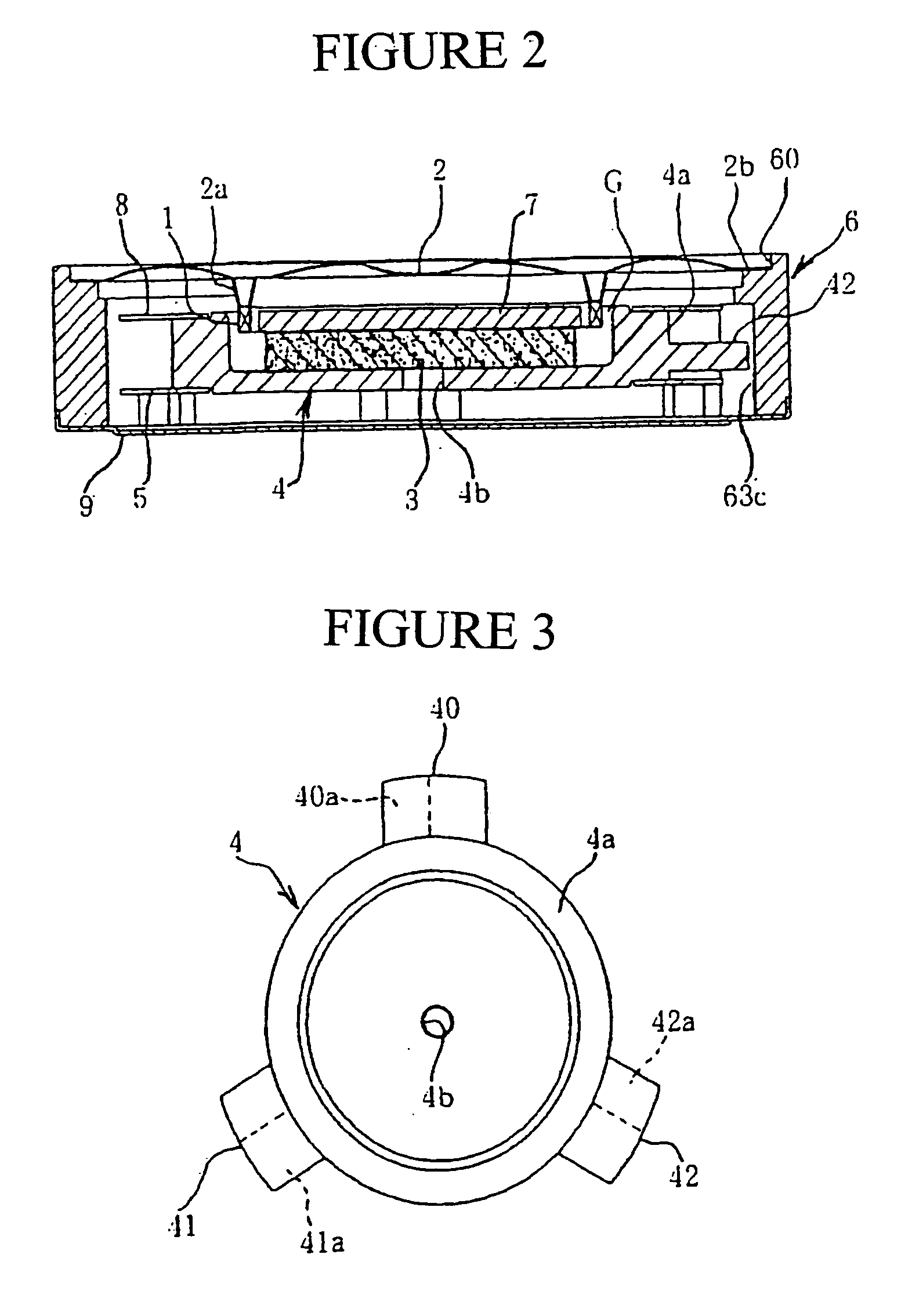
[0047] Embodiment 1 of the present invention is explained below with reference to FIGS. 1 to 17. The vibrating actuator shown in FIG. 1 is provided with coil 1 for applying current, diaphragm 2 that fastens coil 1, magnet 3 for formation of a magnetic circuit, magnetic yoke 4 that holds magnet 3, and oscillation plate 5 that supports magnetic yoke 4. Each of these is assembled within the frame of case 6.

[0048] In addition to aforementioned constituent units in the mode of the embodiment that is presented here, this unit is also provided with disk-shaped pole piece 7 that overlaps the top of magnetic yoke 4, oscillation plate 8 that is assembled on the opposite side from oscillation plate 5 relative to magnetic yoke 4 supporting magnet 3, and metal cover 9 that is fitted to the frame on the opposite side from the frame of case 6 that engages diaphragm 2.

[0049] A circular voice coil to which high frequency current or low frequency current is selectively applied is...

case 6

[0060] Case 6 is formed into a circular frame shape from resin such as polybutylene terephthalate (PBT). Step 60 that fits diaphragm 2 at peripheral edge 2b is installed in the frame edge of In addition, notched steps 61a, 62a that attach oscillation plates 5, 8 via projections 51c, 52c, 53c, 81c, 82c, 83c and depression 63a (only one is shown) that accepts the projection edges of flanges 40, 41, 42 while maintaining a gap as discussed below are installed on the inner surface from the frame edge.

[0061] Metal cover 9 that is engaged by peripheral edge 9a on the frame edge opposite from the frame edge engaging diaphragm 2 is fitted to case 6. Cover 9 is made of metal. It is engaged to the outer peripheral edge on the side opposite from the frame edge of case 6 that engages diaphragm 2. Vent holes 9b that modify the acoustic characteristics due primarily to high frequency are installed in the plate surface of this cover 9, as shown in FIG. 1.

[0062] The acoustic characteristics can be ...

embodiment 2

[0077] (Embodiment 2)

[0078] The second embodiment is explained through FIGS. 18, 19 and 20. Those structures that are identical with the structures in Embodiment 1 are given the same number and an explanation of them is omitted. Damper material 11 for controlling vibration that is placed between oscillation plate 5 and cover 9' as shown in FIG. 19 is attached by bonding onto the lower inner surface in the vibrating actuator shown in FIG. 18.

[0079] Rubber or spongy elastic plate comprising disc-shaped body plate 11a of prescribed thickness and a plurality of projections 11b rising from body plate 11a toward oscillation plate 5 that is attached complete damper material 11. The body plate 11a of the elastic plate 11 is installed and fixed on depression of the inner bottom surface of cover 9'.

[0080] A vibrating actuator with such a structure can be attached to a portable electronic device such as a pager or portable telephone by bringing the attachment side of cover 9' close to the case...


PUM


Abstract

An improved vibrating actuator for notifying the user of a call upon signal arrival by any of a buzzer, a speech and a vibration, and a power supply mechanism thereof. The device has high impact resistance by a magnetic yoke having a flange, a damper material is provided between an oscillation plate and a cover to prevent generation of noise, and a hole is provided in the cover to change acoustic characteristics as required within the same frequency band. As a power supply mechanism for ensuring electrical connection, a projecting electrical connection terminal is provided on the actuator side, and a conductive material touching with the electrical connection terminal is provided as a power supply terminal electrically connected to a power supply section of a circuit board.

Description

INDUSTRIAL FIELD OF INVENTION[0001] The present invention concerns an improved vibrating actuator and a power supply mechanism thereof, comprising a call notification means that notifies of a call upon signal arrival by any of a buzzer, speech or vibration, and a portable electronic device such as a pager or a portable telephone.BACKGROUND TECHNOLOGY[0002] Generally, a vibrating actuator fitted to a portable electronic device is provided with a coil for current application, a diaphragm fastened at one side of the coil, a magnet to form a magnetic circuit, a magnetic yoke supporting this magnet, and an oscillation plate that supports this magnetic yoke. A diaphragm is mounted within the frame of a case by a lip with a magnetic gap between the coil and the magnetic yoke, and an oscillation plate is mounted within the frame of the case at an edge. A cover over the mounting side of an oscillation plate is fitted to the case. Vibration is generated from the oscillation plate at low frequ...

Claims


Application Information

Patent Timeline
Patent Type & Authority Applications(United States)
IPC IPC(8): B06B1/04G10K9/13G10K9/18G10K9/22
CPCB06B1/045G10K9/13H04R2400/07G10K9/22H04R2400/03G10K9/18B06B1/04
Inventor UEDA, MINORUKYONO, TSUNEOYOSHINARI, TERUOFUJIMORI, FUMIO
Owner NAMIKI PRECISION JEWEL CO LTD
Learn More