
Laser apparatus in which laser diodes and corresponding collimator lenses are fixed to block, and fiber module in which laser apparatus is coupled to optical fiber

a laser diode and laser diode technology, applied in the field of laser apparatus, can solve the problems of high manufacturing cost and maintenance cost of excimer lasers, large size of excimer lasers, and low wavelength conversion efficiency

Inactive Publication Date: 2004-02-12
FUJIFILM HLDG CORP +1
View PDF14 Cites 79 Cited by
  • Summary
  • Abstract
  • Description
  • Claims
  • Application Information

AI Technical Summary

Benefits of technology

[0029] A third object of the present invention is to provide a laser apparatus in which a plurality of laser diodes and a plurality of collimator lenses are accurately positioned so that light-emission points of the laser diodes are aligned along a direction, the focal points of the collimator lenses coincide with the light-emission points of the laser diodes, and the lines each passing through one of the light-emission points and a center of a corresponding one of the collimator lenses are parallel to each other.
[0090] In this case, a great number of laser diodes can be arranged with high density. Therefore, it is possible to make a great number of laser beams enter a single multimode optical fiber, and obtain an optically multiplexed laser beam with higher output power.

Problems solved by technology

However, the excimer lasers are large in size, and the manufacturing costs and maintenance costs of the excimer lasers are high.
In the wavelength conversion lasers which convert infrared light into a third harmonic in the ultraviolet range, the wavelength conversion efficiency is very low.
Therefore, it is very difficult to achieve high output power.
In addition, since an optical wavelength conversion element is used in the above wavelength conversion laser, and the optical wavelength conversion element is expensive, the manufacturing cost of the wavelength conversion laser is high.
On the other hand, since it is difficult to obtain a low-dislocation GaN crystal substrate, an attempt has been made to achieve high output power and reliability in a GaN-based compound semiconductor laser.
However, even in the attempt, it is difficult to obtain a low-dislocation substrate having a large area.
Therefore, no GaN-based compound semiconductor laser having a high output power of 500 mW to 1 W has yet been commercialized.
In another attempt to increase output power of a semiconductor laser, for example, it has been considered to form a hundred cavities each of which outputs light with 100 mW so as to obtain a total output power of 10 W. However, it is almost unrealistic to manufacture as many as 100 cavities with high yield.
In particular, it is difficult to manufacture GaN-based compound semiconductor lasers each having many cavities since manufacture of GaN-based compound semiconductor lasers with a high yield of 99% or greater is difficult even when the GaN-based compound semiconductor lasers each have a single cavity.
When the above positioning is inaccurately performed, it is impossible to make the plurality of laser beams converge on a small spot.
Therefore, for example, when a photosensitive material is exposed to the laser beams in order to form an image, it becomes impossible to form a fine image by the exposure.
If the laser diodes and the collimator lenses are inaccurately positioned, it becomes impossible to make the plurality of laser beams converge on a sufficiently small spot.
Although a method for adjusting the position of each lens during activation of the laser diodes is known, it is not easy to adjust the position of each lens by moving the lens in the X, Y, and Z directions relative to a corresponding laser diode, since there is no sufficient space for equipment which securely holds the lenses.
Therefore, even in the case where the reliability of fixation at each place of fixation is increased, it is very difficult to achieve a satisfactory yield when the number of places of fixation increases.
However, due to inaccuracy of the individual parts, the parallelism between the holder element, the lenses, and the laser diode block is not necessarily compatible with the alignment between optical axes of the lenses and the laser diodes, and therefore it is difficult to ensure precision.
Thus, the alignment yield decreases, alignment time and parts cost increase, and the total cost of the laser apparatus also increases.
Therefore, it is impossible to accurately arrange the optical fiber so as to align the optical fiber with a position at which the laser beams converge.
As explained before, in the conventional lens adjustment, the number of places at which the laser diodes and the collimator lenses are fixed is twice the number of laser beams which are optically multiplexed, and therefore it is difficult to ensure reliability.

Method used


Image

  • Laser apparatus in which laser diodes and corresponding collimator lenses are fixed to block, and fiber module in which laser apparatus is coupled to optical fiber
  • Laser apparatus in which laser diodes and corresponding collimator lenses are fixed to block, and fiber module in which laser apparatus is coupled to optical fiber
  • Laser apparatus in which laser diodes and corresponding collimator lenses are fixed to block, and fiber module in which laser apparatus is coupled to optical fiber

Examples


first embodiment

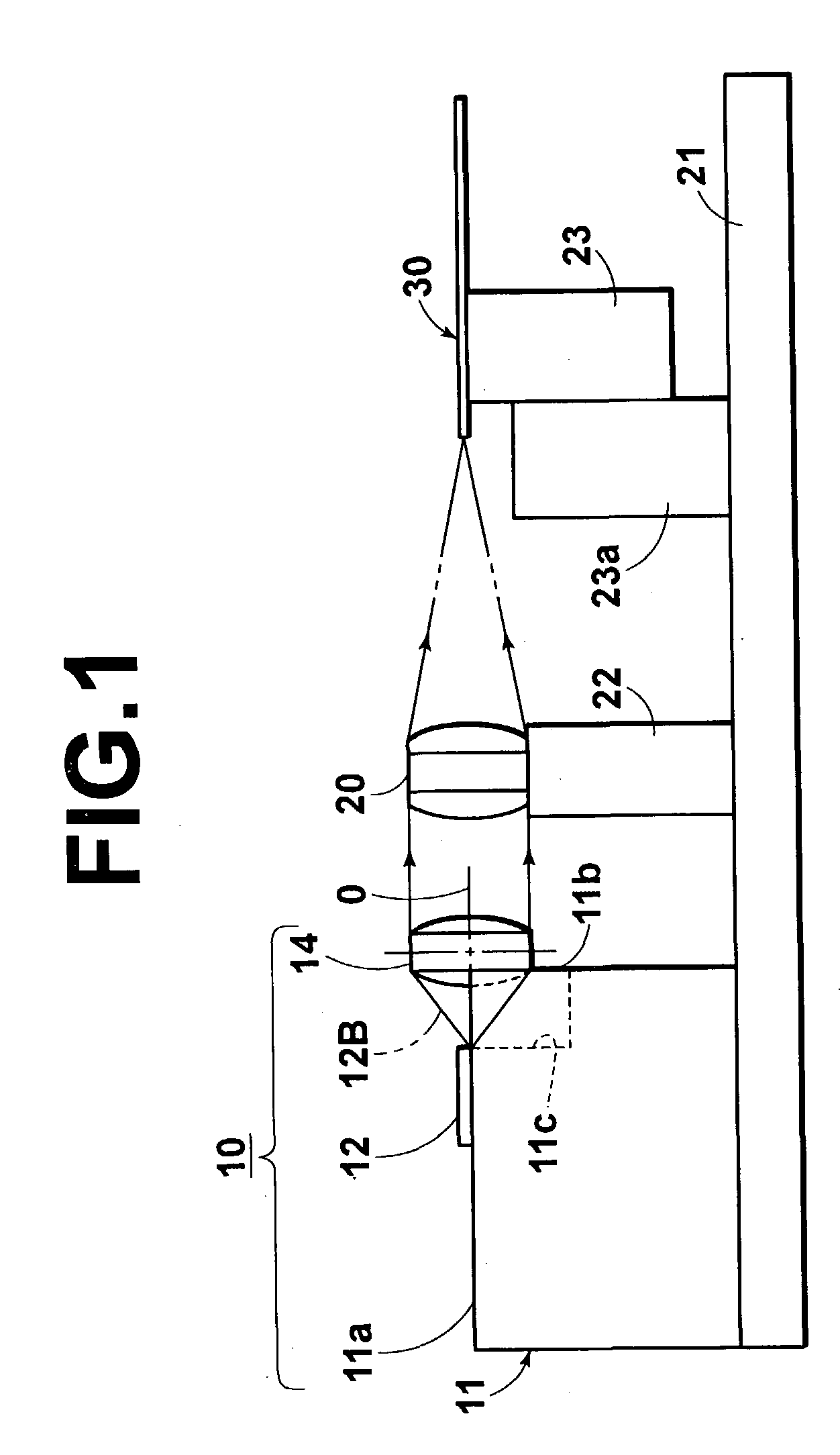
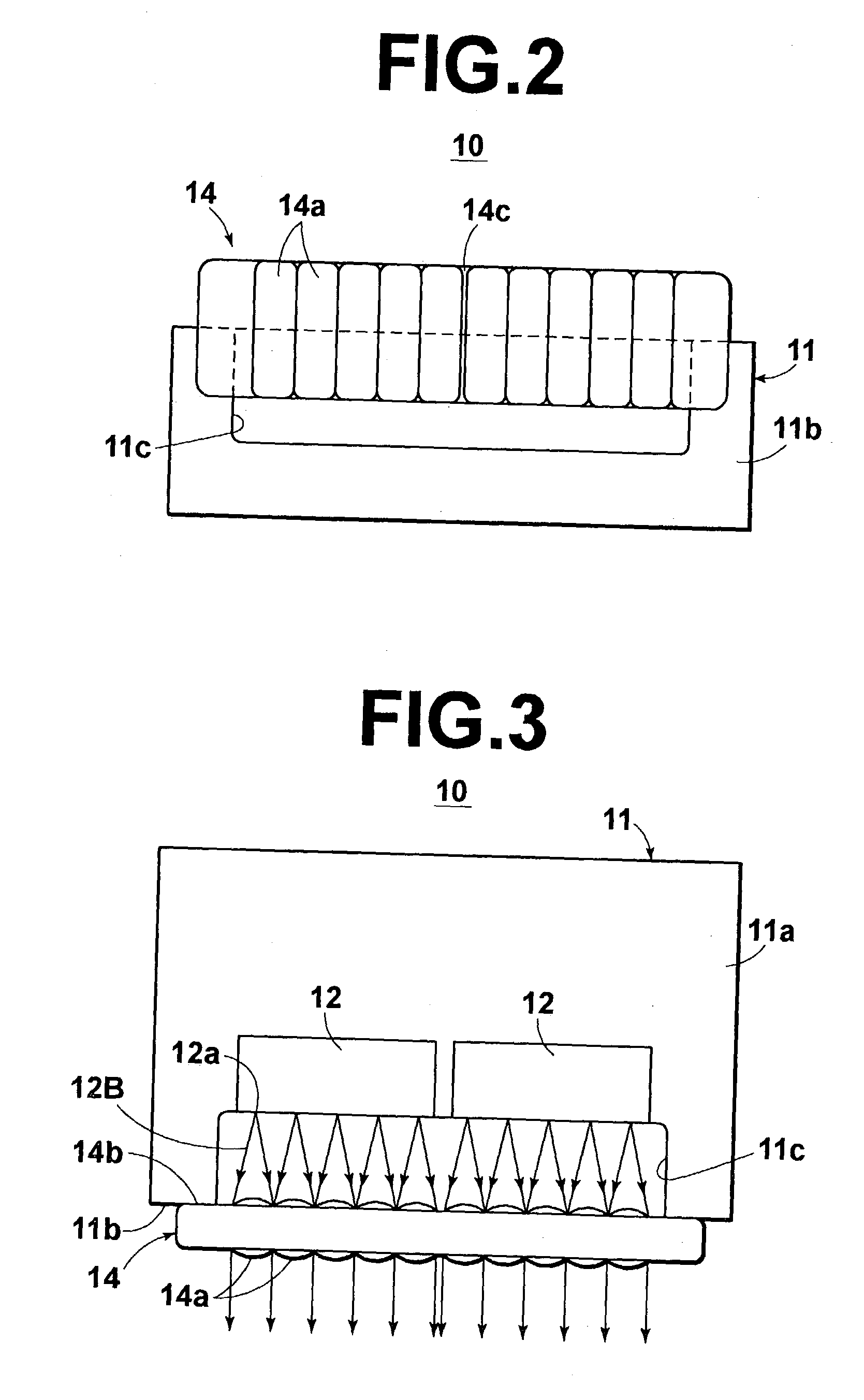
[0137] FIG. 1 is a side view of a fiber module using a laser apparatus according to the first embodiment of the present invention, and FIGS. 2 and 3 are front and plan views of the laser apparatus used in the fiber module of FIG. 1. The fiber module of FIG. 1 realizes an optically-multiplexing laser-light source. As illustrated in FIGS. 1, 2, and 3, the laser apparatus 10 according to the first embodiment comprises, for example, two multicavity laser-diode chips 12 and a collimator-lens array 14 which are fixed to a heat block (stem) 11. The heat block 11 is made of copper, and the collimator-lens array 14 is made of synthetic resin or glass.

[0138] For example, the multicavity laser-diode chips 12 each contain GaN-based laser diode having five cavities (five light-emission points 12a) and an identical oscillation wavelength of 405 nm. The multicavity laser-diode chips 12 are arranged along the same direction as the direction along which the light-emission points 12a are aligned. In ...

second embodiment

[0155] The second embodiment of the present invention will be explained below.

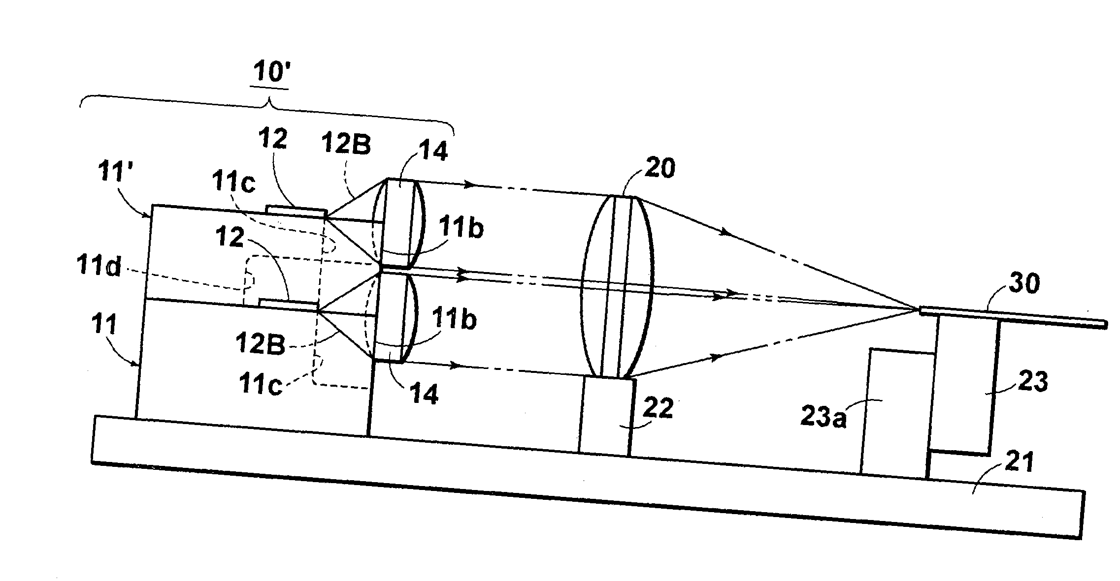
[0156] FIG. 4 is a side view of a fiber module using a laser apparatus 10' according to the second embodiment of the present invention, and FIG. 5 is a front view of the laser apparatus 10' used in the fiber module of FIG. 4. The fiber module of FIG. 4 realizes an optically-multiplexing laser-light source. In FIGS. 4 and 5, elements having the same functions as the elements in the fiber module illustrated in FIG. 1 bear the same reference numerals as FIGS. 1 through 3, respectively, and are not explained below unless necessary. In addition, since the plan view of the laser apparatus 10' according to the second embodiment is basically the same as the plan view (FIG. 3) of the laser apparatus 10 according to the first embodiment, the plan view of the laser apparatus 10' is not shown.

[0157] The laser apparatus 10' according to the second embodiment is different from the laser apparatus 10 illustrated in FIGS....

third embodiment

[0160] The third embodiment of the present invention is explained below.

[0161] FIGS. 6 and 7 are side and front views of a laser apparatus 10" according to the third embodiment of the present invention. The laser apparatus according to the third embodiment can be used for constructing an optically-multiplexing laser-light source. In FIGS. 6 and 7, elements having the same functions as the elements in the laser apparatuses illustrated in FIGS. 1 through 5 bear the same reference numerals as FIGS. 1 through 5, respectively, and are not explained below unless necessary. Since the plan view of the laser apparatus 10" according to the third embodiment is basically the same as the plan view (FIG. 3) of the laser apparatus 10 according to the first embodiment, the plan view of the laser apparatus 10" is not shown.

[0162] The laser apparatus 10" according to the third embodiment is different from the laser apparatus 10 illustrated in FIGS. 1 through 3 in that three layers in each of which tw...


PUM


Abstract

A laser apparatus includes: a plurality of laser diodes respectively having light-emission points and being fixed to a block so that the light-emission points are aligned along a direction; and a collimator-lens array integrally formed to contain a plurality of collimator lenses which are arranged along a direction and respectively collimate laser beams emitted from the plurality of laser diodes. The block has a lens-setting surface which is flat, perpendicular to optical axes of the plurality of laser diodes, and located on the forward side of the plurality of laser diodes at a predetermined distance from the light-emission points, and the collimator-lens array is fixed to the block so that an end surface of the collimator-lens array is in contact with the lens-setting surface.

Description

[0001] 1. Field of the Invention[0002] The present invention relates to a laser apparatus in which a plurality of laser diodes are fixedly arranged on a block, and a laser apparatus in which laser beams emitted from a plurality of laser diodes are collimated into a plurality of collimated laser beams which are parallel to each other.[0003] The present invention also relates to a method for producing a laser apparatus in which laser beams emitted from a plurality of laser diodes are collimated into a plurality of collimated laser beams which are parallel to each other.[0004] The present invention further relates to a fiber module comprising a light source and an optical fiber which light emitted from the light source enter.[0005] 2. Description of the Related Art[0006] Conventionally, in order to generate a laser beam having a ultraviolet wavelength, wavelength conversion lasers, excimer lasers, and Ar lasers are used. In the wavelength conversion lasers, infrared light emitted from ...

Claims


Application Information

Patent Timeline
IPC IPC(8): G02B6/42H01S5/00H01S5/022H01S5/40
CPCG02B6/4206G02B6/4249H01S5/0224H01S5/02252H01S2301/04H01S5/4012H01S5/4031H01S5/405H01S5/02284G02B6/424G02B6/4251G02B6/4267H01S5/02251H01S5/02326H01S5/0234
Inventor NAGANO, KAZUHIKOOKAZAKI, YOJIKURAMACHI, TERUHIKOYOSHIDA, TAKASHIMINO, SATOSHISUZUKI, EIJI
Owner FUJIFILM HLDG CORP
Learn More