
Optical glass for precision press molding, preform for precision press molding, and process for the production thereof

a technology of optical glass and press molding, applied in the direction of glass tempering apparatus, instruments, manufacturing tools, etc., can solve the problems of poor suitability for press molding, limited glass to which the above method can be applied, and intense wear or breakage of the above molding surfa

Inactive Publication Date: 2003-11-13
HOYA CORP
View PDF3 Cites 89 Cited by
  • Summary
  • Abstract
  • Description
  • Claims
  • Application Information

AI Technical Summary

Benefits of technology

[0010] Under the circumstances, it is an object of the present invention to provide a high-refractivity low-dispersion optical glass which does not require machining of an optical-function surface, such as polishing or lapping, after precision press molding thereof and which is used for producing an optical element, a precision press molding preform made of the above optical glass, an optical element made of the above glass, and processes for the production of the above preform and the above optical element.

Problems solved by technology

However, the above optical glasses aim at an improvement in devitrification resistance, and there is therefore involved a problem that expensive components such as Lu.sub.2O.sub.3, etc., are essential, or that a large amount of Sb.sub.2O.sub.3 that is a harmful component is essentially incorporated, for improving such optical glasses in stability.
Further, of glass compositions disclosed in the above Publications, compositions that can attain a refractive index nd>1.8 and an Abbe's number .nu.d>35 very useful for optical designing contain almost no ZnO or Li.sub.2O that is said to be effective for decreasing the glass transition temperature, so that they have poor suitability to press molding.
Generally, a glass having such optical constants has a large content of rare earth metal oxide component and has a low degree of stabilization against devitrification, so that it has been difficult to develop a composition that makes it possible to decrease the glass transition temperature to a region in which the glass can be press molded economically.
However, the glass to which the above method can be applied is limited to a glass that can undergo plastic deformation at a relatively low temperature.
When a glass having a high glass transition temperature is used, the molding surface of a press-shaping mold is exposed to a high temperature during the precision press molding, so that the above molding surface is intensely worn or broken.
In the precision press molding, even a fine flaw that occurs on the molding surface of a press-shaping mold is transferred to the optical-function surface of an optical element that is an end article, which means that the function of the optical element is impaired.
The glass transition temperature of the glass that is usable is therefore limited to 630.degree. C. or lower.
Further, when the content of Sb.sub.2O.sub.3 is large, the molding surface of the press-shaping mold may be damaged during precision press molding.
PbO is a component that can be easily reduced, so that the surface of a molded product comes to be cloudy due to a deposit formed by reduction during the precision press.
Further, Lu.sub.2O.sub.3 is a substance having a high scarcity value and is expensive for a raw material for an optical glass, so that it is not any component whose use is desirable.
However, the content of B.sub.2O.sub.3 exceeds 40%, the refractive index of the glass is decreased, and the glass obtained is not suitable for obtaining a high-refractivity glass.
When the content of SiO.sub.2 exceeds 25%, the refractive index of the glass decreases, and further, the glass transition temperature increases, so that precision press molding of the glass is difficult.
However, when the content of La.sub.2O.sub.3 is less than 5%, no sufficient effect is produced, and when it exceeds 20%, the glass is greatly deteriorated in stability against devitrification.
However, when the content of Gd.sub.2O.sub.3 is less than 5%, no sufficient effect can be obtained.
When it exceeds 20%, the stability of the glass against devitrification is deteriorated, and the glass transition temperature increases, so that the precision press molding of the glass is difficult.
When the content of the lanthanoid oxides essential for high refractivity and low dispersion is increased, molding of the glass comes to be impossible.
When the content thereof exceeds 15%, the liquidus temperature sharply increases, and the stability against devitrification is deteriorated.
When the content of WO.sub.3 exceeds 15%, the dispersion becomes large, and the necessary low-dispersion property can be no longer obtained.
When the content of each of individual components exceeds 8%, any one of these impairs the stability of the glass against devitrification to a great extent and increases the glass transition temperature and sag temperature.
When the content thereof exceeds 8%, the dispersion becomes large, and the necessary low-dispersion property can be no longer obtained.
However, GeO.sub.2 is expensive and increases the dispersion, so that the content of GeO.sub.2 is preferably 8% or less.
Further, desirably, they do not contain any fluorine in view of volatilization during melting of the glass.
When the weight of a preform is smaller than the weight of an end precision press molded article, the glass is not fully charged in the molding surface of a press-shaping mold during its precision press molding, and there is caused a problem that no intended surface accuracy can be obtained or that the thickness of a molded article is smaller than an intended thickness.
Further, when the weight of a preform is larger than the weight of an end precision press molded article, there is caused a problem that excess glass penetrate gaps of precision press mold members to form burrs, or that a molded article has a larger thickness than an intended thickness.

Method used


Image

  • Optical glass for precision press molding, preform for precision press molding, and process for the production thereof
  • Optical glass for precision press molding, preform for precision press molding, and process for the production thereof
  • Optical glass for precision press molding, preform for precision press molding, and process for the production thereof

Examples


examples 1-64

[0074] Oxides, carbonates, sulfates, nitrates, hydroxides, etc., such as SiO.sub.2, H.sub.3BO.sub.3, La.sub.2O.sub.3, ZnO, ZnCO.sub.3, ZrO.sub.2, Li.sub.2CO.sub.3, etc., as raw materials were provided, and 250 to 300 g of each of these components was weighed so as to form compositions shown in Tables 1 to 7. These raw materials in each Example were fully mixed to prepare a formulated batch, the formulated batch was placed in a platinum crucible, and the formulated batch was melted in air in an electric furnace maintained at 1,200 to 1,450.degree. C., with stirring for 2 to 4 hours. After melted, the glass melt was allowed to flow into a 40.times.70.times.15 mm mold made of carbon and allowed to cool to a glass transition temperature, and immediately thereafter, the glass was placed in an annealing furnace and annealed in a glass transition temperature range for about 1 hour. Then, the glass in the furnace was allowed to cool to room temperature, to give an optical glass. In the thus...

example 65

[0087] Precision press molding preforms were produced from the optical glasses obtained in Examples 1 to 64 as follows. First, melting, refining and homogenization were carried out to obtain a molten glass that was to give one of the above optical glasses, the molten glass was dripped from a flow nozzle made of a platinum alloy toward a receiving member, and in a concave portion of the receiving member, the received molten glass drop was floated and rolled while a gas was ejected upward from a gas ejection port formed in a bottom of the concave portion, to shape the molten glass into a preform (Method 1). The thus-formed preforms from the above optical glasses had a weight equivalent to the weight of an intended end product, underwent no devitrification and had a smooth surface free of defects such as a flaw, soiling and alteration.

[0088] Separately, the same molten glass drop as above was dropped from the flow nozzle in the same manner as above into liquid nitrogen and shaped into ...

example 66

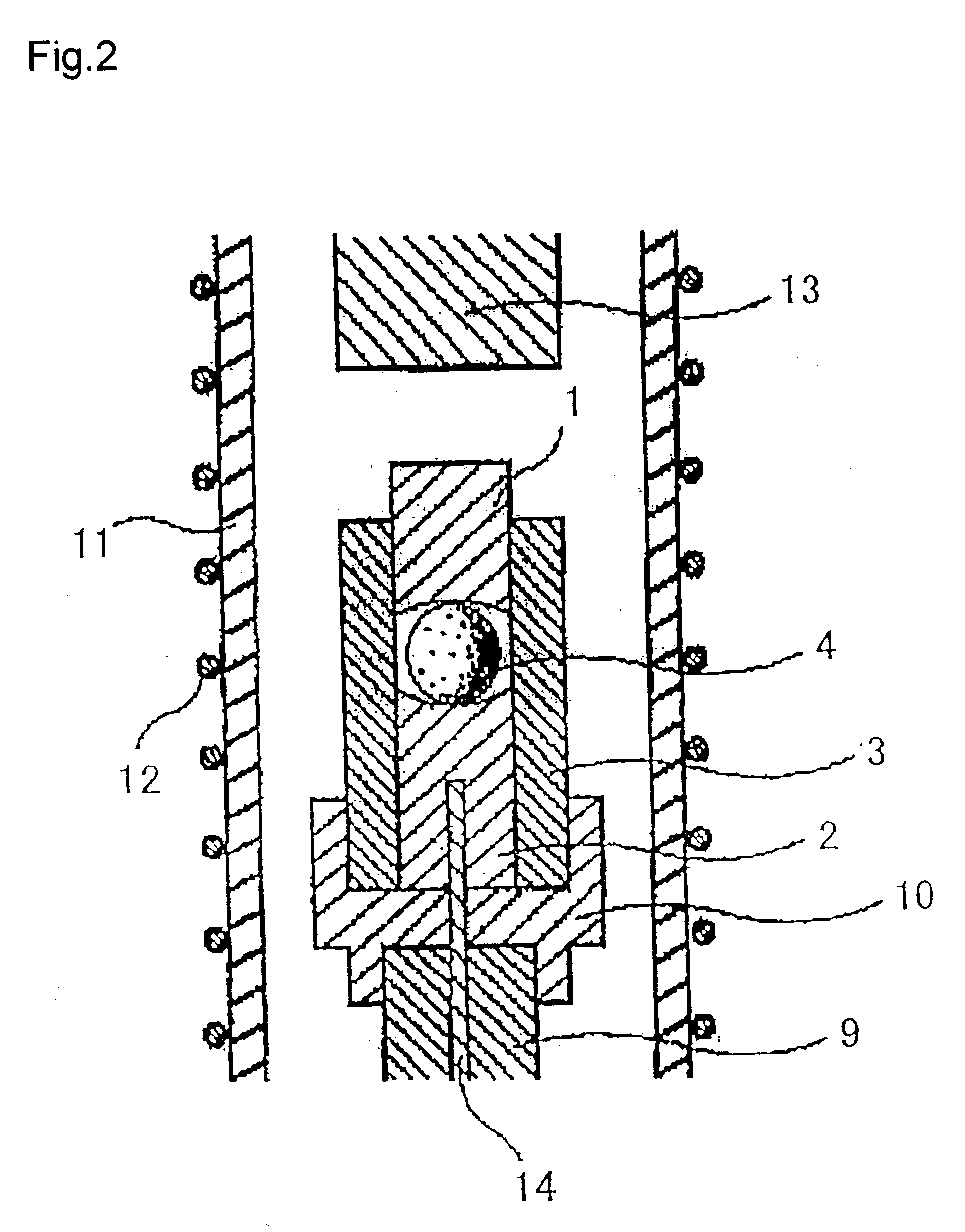
[0090] Each of the spherical preforms made of the optical glasses of Examples 1 to 64 obtained by Method 1 in Example 65 was heated and precision press molded (aspherical-precision pressed) with an apparatus shown in FIG. 2, to give aspherical lenses.

[0091] Particulars of the precision press molding were as follows. The preform 4 was placed between a lower mold member 2 and an upper mold member 1 which had an aspherical form and were made of SiC, then the atmosphere inside a quartz tube 11 was replaced with a nitrogen atmosphere inside, and an electric current was applied to heater 12 to heat the inside of the quartz tube 11. The temperature inside the shaping mold was set at a temperature between a sag temperature of the glass+20.degree. C. and the sag temperature of the glass+80.degree. C., and while this temperature was maintained, a press rod 13 was moved downward to press the upper mold member 1 thereby to press-mold the preform (molding glass gob) in the shaping mold. The pres...


PUM

PropertyMeasurementUnit
glass transition temperatureaaaaaaaaaa
refractive index ndaaaaaaaaaa
refractive indexaaaaaaaaaa

Abstract

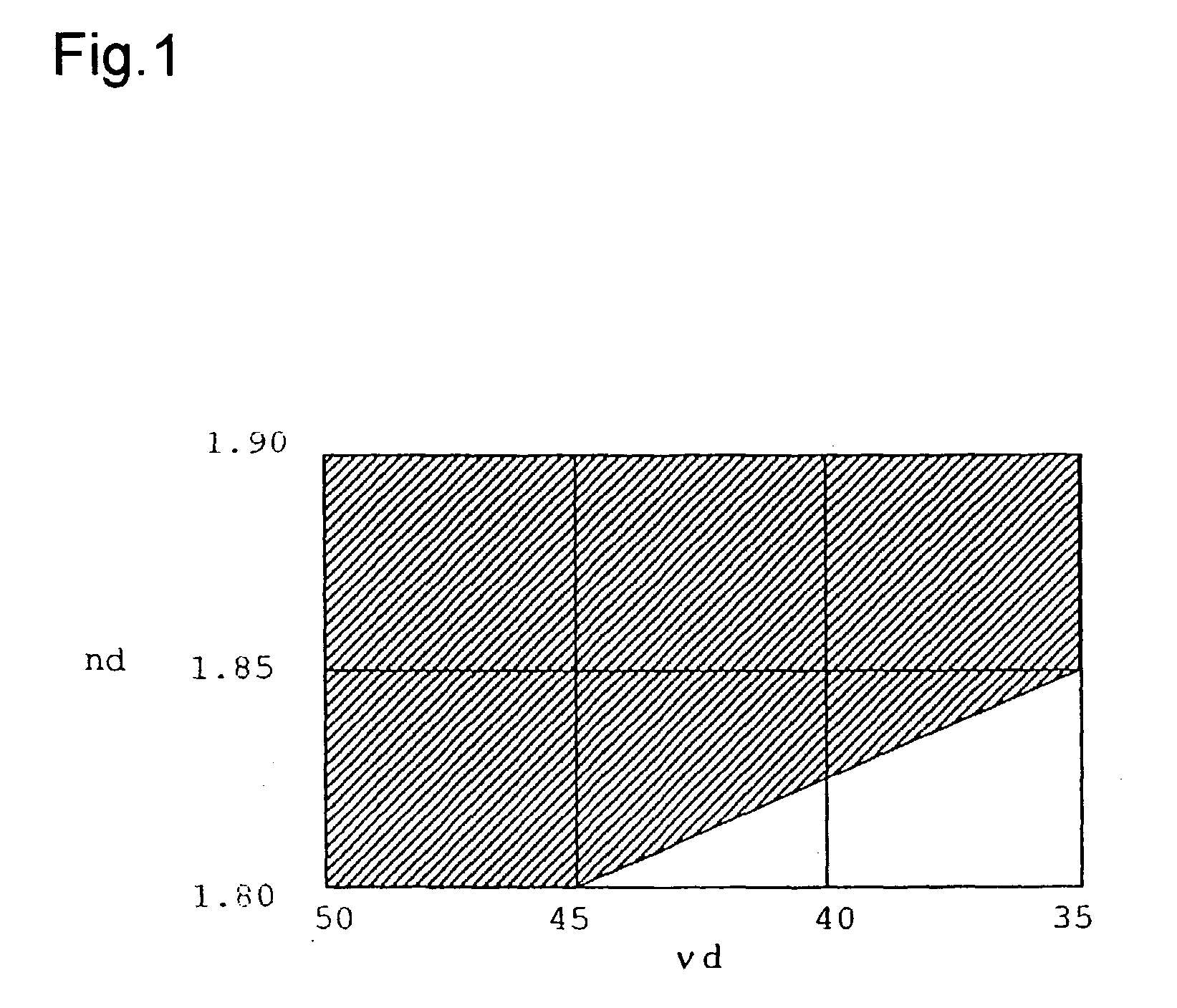
A high-refractivity high-dispersion optical glass for producing an optical element, which requires no machining, such as polishing or lapping, of an optical-function surface after precision press molding, containing B2O3, SiO2, La2O3, Gd2O3, ZnO, Li2O, ZrO2 and Ta2O5 as essential components, containing 0 to 1 mol % of Sb2O3 as an optional component, substantially containing none of PbO and Lu2O3, having a glass transition temperature of 630° C. or lower, and (1) having a refractive index nd and an Abbe's number nud which satisfy all of the following relational expressions, 1.80<nd<=1.90, 35<nud<=50, and nd>=2.025-(0.005xnud) or (2) having an nd of greater than 1.85 and a nud of greater than 35.

Description

TECHNICAL BACKGROUND[0001] 1. Field of the Invention[0002] The present invention relates to an optical glass for precision press molding, a preform for precision press molding, an optical element, and processes for the production of the preform and the optical element. More specifically, the present invention relates to a high-refractivity low-dispersion optical glass which does not require machining of an optical-function surface such as polishing or lapping after precision press molding thereof and which is used for producing an optical element such as an ultra-precision aspherical lens, a precision press molding preform made of the optical glass, an optical element made of the same, and processes for the production of the above preform and optical element.[0003] 2. Prior Art[0004] In recent years, digital cameras have appeared, and as the integration and function of machines and devices using an optical system are rapidly enhanced, it is increasingly demanded to enhance the preci...

Claims


Application Information

Patent Timeline
Patent Type & Authority Applications(United States)
IPC IPC(8): B29C43/02B29C43/36G02B1/00C03B11/00C03B11/08C03C3/068
CPCB29C43/021B29C43/361B29C2043/3618B29L2011/0016C03B11/005C03C3/068C03B11/084C03B2215/07C03B2215/66C03B2215/72C03B11/08
Inventor HAYASHI, KAZUTAKAZOU, XUELU
Owner HOYA CORP
Learn More