
Microwave defrosting under reduced pressure

a technology of microwave defrosting and reduced pressure, which is applied in the direction of electric/magnetic/electromagnetic heating, domestic stoves or ranges, lighting and heating apparatus, etc., can solve the problems of difficult to achieve uniform irradiation, difficulty in accurately establishing microwave irradiation time, and marked loss in the quality of frozen products

Inactive Publication Date: 2002-12-26
ELLIE CORP
View PDF0 Cites 1 Cited by
  • Summary
  • Abstract
  • Description
  • Claims
  • Application Information

AI Technical Summary

Benefits of technology

[0015] Further, one cause of the generation of dripping is due to a temperature difference between the inside portion and the outside portion of the frozen products. In this connection, when the frozen products are being heated with microwave radiation, the outer portion of the frozen products receive more microwave heating than the inner portion, and this results inevitably in the outer portion having a higher temperature than the inner portion. Further, because microwave radiation penetrates into frozen products from the outside portion thereof, the risk of the outside portion of the frozen products changing into liquid water must normally be taken into consideration. This problem can be solved by making the temperature of the inside portion of the frozen product and the temperature of the outside portion of the frozen product as close as possible. The present invention achieves this by generating sublimation at the outer port-ion of the frozen products at a minute level that reduces the temperature of the outer portion of the frozen products without affecting the product quality. By repeating this process, the temperature difference between the inner portion and the outer portion of the frozen products can be made gradually smaller.
[0035] Further, the relationship discovered in the present invention related to reduced pressure, the frozen products and microwave-induced electrical discharges makes it possible to vastly improve defrosting control, and is extremely advantageous with regards to reliability and accuracy regardless of the type, shape and temperature of the frozen products. Accordingly, the present invention makes it possible to carry out defrosting in a short amount of time while maintaining a high level of product quality.

Problems solved by technology

Further, in the expensive fish meat selling industry related to tuna and the like, frozen tuna at -60.degree. C. is defrosted by being immersed in warm salt water at 40.degree. C.
As soon as this drip begins to flow, the microwave radiation will concentrate at such location, thereby causing the region where the drip is occurring to be overheated even though temperature inside the frozen products is -10.degree. C., and this results in a marked loss in the quality of the frozen products.
However, uniform irradiation is difficult to achieve with frozen products that have irregular shapes and sizes, and there is the further difficulty involved in accurately establishing microwave irradiation time when the frozen products have various shapes.
Accordingly, the problem of dripping can frequently occur when defrosting is carried out to a relatively high temperature such as -1.degree. C. or -2.degree. C.
Furthermore, neither the method of letting frozen products stand over time in a refrigerator nor the method of immersing frozen products in warm salt water can avoid the problem of dripping, and for this reason, frozen products defrosted by these methods will suffer a loss in quality.
In this regard, the problem usually associated with microwave heating is knowing when to properly terminate the microwave heating.
Further, one cause of the generation of dripping is due to a temperature difference between the inside portion and the outside portion of the frozen products.
In this connection, when the frozen products are being heated with microwave radiation, the outer portion of the frozen products receive more microwave heating than the inner portion, and this results inevitably in the outer portion having a higher temperature than the inner portion.
Further, because microwave radiation penetrates into frozen products from the outside portion thereof, the risk of the outside portion of the frozen products changing into liquid water must normally be taken into consideration.
Consequently, because there is a change in the pressure level that needs to be achieved due to the amount of sublimation being generated from the frozen products, there is no way accurate control can be carried out based on the pressure reaching the prescribed pressure level.
Next, it is believed that dripping is most likely to occur at the parts of the frozen products that come in contact with the support jig holding the frozen products.
However, even in the case where direct microwave heating of the support jig is avoided by constructing the support jig from a material having a high microwave permeability or high microwave reflectivity, the temperature of the support jig is close to that of the atmosphere inside the pressure reducing chamber, and this allows heat to be transferred from the support jig to the parts of the frozen products in contact with the support jig, thereby causing a temperature rise in the parts of the frozen products in contact with the support jig.
Further, in the case where too high of a microwave output level is used for the weight of the frozen products, microwave radiation will concentrate at the protruding parts of the outside portion of the frozen products and cause overheating thereof, which in turn can cause the formation of liquid water.
On the other hand, the presence of only a very small amount of liquid water causes the microwave radiation to concentrate at the location of such liquid water, and because this takes away almost all the microwave heating of the frozen products, the defrosting process is interrupted.
As a result, it was found that only a very small temperature increase occurred in the frozen sample, and this made defrosting impossible.
Consequently, such experiments confirmed that even a small amount of dripping from the frozen products will make defrosting difficult.
For example, even when the temperature of the outside portion of the frozen products is -1.degree. C., the temperature of the inside portion can be as low as -8.degree. C., and this is believed to be one cause of the generation of dripping.
However, the error due to the clearance of the vacuum pump normally makes it difficult to reach the prescribed pressure level, and the pressure level that can be reached will change depending on the amount of sublimation vapor generated from the frozen products.
Namely, when sublimation is generated from the frozen products in a prescribed pressure range, the higher the temperature of the frozen products, the greater the amount of sublimation vapor created, and this makes it difficult to reach low pressure levels.
Consequently, because this results in heat being transferred from the jig to the frozen products, the greater the contact area between the jig and the frozen products, the more likely dripping will occur at such contact areas.
This is due to the fact that it is not possible to accurately measure the generation of sublimation if measurements are made in units of roughly 1 torr, and such inaccuracy would make it difficult to prevent overdrying of the surface of the frozen products.
For example, because high quality defrosting has been difficult up to now in the meat industry, there has been a tendency to Switch from frozen transport to chilled transport.
However, chilled transport has a shorter freshness period, and this together with the other disadvantages of chilled transport leads to high transportation costs.
Further, in the high-quality fresh fish industry which sells Japanese sashimi, there was a limit to how much fish could be defrosted by prior art defrosting methods, and such methods usually created large defrosting losses.

Method used


Image

  • Microwave defrosting under reduced pressure
  • Microwave defrosting under reduced pressure
  • Microwave defrosting under reduced pressure

Examples


specific embodiment 1

[0106] Specific Embodiment 1

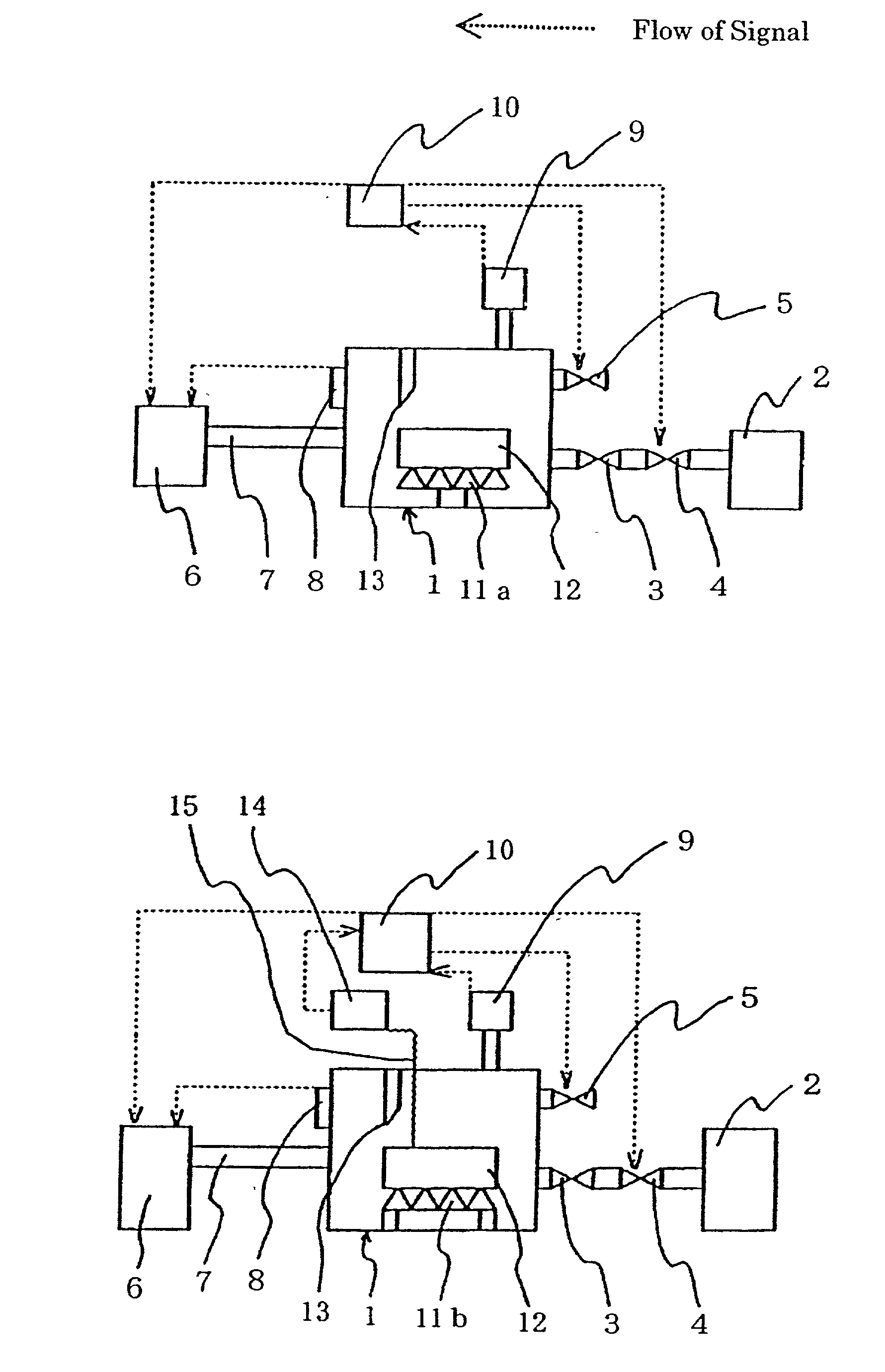
[0107] Six kilograms of frozen beef in the form of three 2-kg blocks were placed inside a stainless steel pressure reducing chamber 1 having a width of 600 mm, a height of 600 mm and a depth of 700 mm, and then defrosting was carried out. During such defrosting process, a vacuum pump2, for example, dry pump was used at an output level of 3 kW to reduce the pressure toward a target pressure level of 1.5 torr, microwave heating was carried out at an output level of 0.6 kW, and changes in pressure were brought about using a pressure adjustment valve 4 in a manner that did not introduce air into the pressure reducing chamber during the defrosting process. Further, the pressure was measured in units of 0.1 torr, and the frozen beef was supported by two triangular bars made of fluororesin to create line contact or point contact, whereby the contact area between the bar and the frozen beef was made very small. The temperature of the frozen beef at the beginning ...

specific embodiment 2

[0109] Specific Embodiment 2

[0110] Eight kilograms of frozen tuna in the form of four 2-kg blocks were defrosted under conditions similar to those described in Specific Embodiment 1. However, in this case microwave heating was carried out at an output level of 0.7 kW. In this connection, because these blocks include skin and bones at harvest time, if they can be defrosted while maintaining a high quality, the defrosted product will yield 5.about.10% sashimi or sushineta. In the test conducted in this embodiment, the temperature of the frozen tuna at the beginning of the defrosting process was -55.degree. C. Further, the control of the termination of defrosting was carried out in accordance with the method of claim 8. A summary of the defrosting process is shown in the table below.

2TABLE B Time of Microwave Variation of Electrical Discharge Chamber Pressure Heating Temperature at Chamber Pressure after 30 sec. At4torr 1.sup.st Microwave Heating -55.0.degree. C. .fwdarw. -32.8.degree....

specific embodiment 3

[0112] Specific Embodiment 3

[0113] Thirty kilograms of frozen pork in the form of three 10-kg blocks were hung on a stainless steel rotatable jig using thin polypropylene cord, and then defrosting was carried out as this jig was rotated inside a stainless steel pressure reducing chamber having a width of 1,000 mm, a height of 1,200 mm and a depth of 1,200 mm. In this case, because a rotating jig was used, temperature measurements of the inside portion could not be carried out using an optical fiber thermometer. Further, an oil-sealed rotary vacuum pump was used at an output level of 5.5 kW, and microwave heating was carried out at an output level of 1.8 kW. In the test conducted in this embodiment, the temperature of the frozen pork at the beginning of the defrosting process was -40.degree. C. Further, the control of the termination of defrosting was carried out in accordance with the method of claim 7. In this regard, with a target weight loss of 0.8% established for termination of...


PUM


Abstract

It is an object of the present invention to provide a method and apparatus for carrying out high quality defrosting in a short amount of time which creates only a small temperature difference between the inside and outside of the frozen products, with very little oxidation of the frozen products, and without generating a drip from the frozen products regardless of the shape and temperature of the frozen products. A method of defrosting frozen products of the present invention is the method of carrying out microwave heating while reducing the pressure, terminating microwave heating upon detection of a microwave-induced electrical discharge during the microwave heating step, reducing the pressure while microwave heating is in a terminated state to a pressure level at or below a sublimation pressure level to generate sublimation on the frozen products, returning the pressure to a prescribed pressure level to enable microwave heating to be restarted, and repeating the steps from the microwave heating step through the pressure returning step a prescribed number of times.

Description

[0001] 1. Field of the Invention[0002] The present invention relates to defrosting technology designed to prevent dripping and the loss of quality in the defrosted products. In particular, the present invention relates to defrosting technology in which high-quality defrosting is performed in an extremely short amount of time by carrying out low-energy microwave heating at reduced pressure. Further, the defrosting technology of the present invention can be used in various industries, including the food industry, pharmaceutical industry, cosmetic industry, cattle raising industry, marine products industry, machine manufacturing industry and home electronics manufacturing industry.[0003] 2. Description of the Prior Art[0004] In prior art defrosting methods that use microwave heating at reduced pressure, microwave heating is carried out after the pressure has been reduced to a prescribed level (e.g., 25 torr) in order to prevent the product temperature from becoming too high during defr...

Claims


Application Information

Patent Timeline
IPC IPC(8): A23L3/40A23L3/365A47J27/088F24C7/02H05B6/68
CPCH05B6/6467
Inventor YAGI, SHUNICHISHIBATA, KAZUO
Owner ELLIE CORP
Learn More