Production method for continuous casting cast billet

a production method and technology of casting billet, applied in casting apparatus, manufacturing tools, melt holding vessels, etc., can solve the problems of reducing the yield of a product, difficult to stably manufacture the cast piece in the method, and malfunction in production, so as to increase the effect of forming the local flowing portion and the damping effect of the stream

Inactive Publication Date: 2002-10-31
KAWASAKI STEEL CORP
View PDF0 Cites 3 Cited by
  • Summary
  • Abstract
  • Description
  • Claims
  • Application Information

AI Technical Summary

Benefits of technology

0118] Further, it is preferable to dispose the lower ejection hole above the center of the magnetic pole in order to increase the effect of forming the local flowing portion and the damping effect of the stream from the lower ejection hole.
0119] When the strength of the applied magnetic field is too small, there is a possibility that the molten steel in the upper pool is blended with the molten steel in the lower pool because the braking effect performed by the magnetic field is weakened. In contract, when the strength is too large, the flow of the molten steel to the upper po...

Problems solved by technology

However, since the method disclosed in the Japanese Examined Patent Application Publication No. 3-20295 includes a very complicated process for separately refining the molten steel used in the surface layer of the cast piece and the molten steel used in the interior thereof, the method is liable to cause malfunction in production.
Moreover, it is difficult to manufacture the cast piece stably in the method because it is necessary to perform very difficult control for independently supplying molten steel from respective tundishes in quantities according to the solidifying speeds thereof above and below the magnetic field zone.
As a result, there is a problem that the yield of a product decreases.
As a result, a problem arises in that an extreme difference of concentration between a portion to which a solute element is added and a portion apart from the above por...

Method used


Image

  • Production method for continuous casting cast billet
  • Production method for continuous casting cast billet
  • Production method for continuous casting cast billet

Examples


example 1

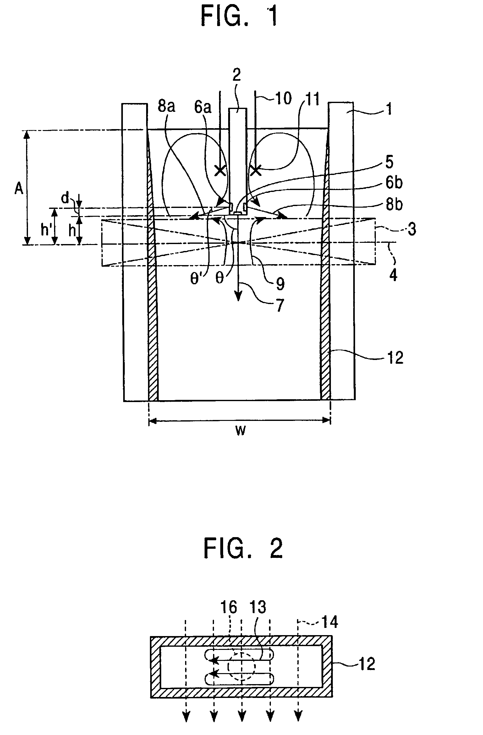
[0125] Direct current magnetic field application position (distance from molten metal level in mold to center of height of magnetic pole)

[0126] A: 0.347 m

[0127] Strength of applied magnetic field: 0.3 T

[0128] Height of magnetic field: 0.15 m

[0129] Immersion nozzle

[0130] Upper ejection hole: 2 holes, size of hole 10*10 mm

[0131] ejection angle .theta.=0.degree. (horizontal)

[0132] Lower ejection hole: single hole, size of hole 28 mm

[0133] dia (circle)

[0134] ejection angle .theta.=90.degree. (vertically downward)

[0135] Immersed depth of lower hole (from molten metal level in mold to lower end of lower ejection hole) 0.34 m

[0136] Immersed depth of upper holes (from molten metal level in mold to center of upper ejection hole) 0.177 m

[0137] Inner diameter of immersion nozzle 0.040 m

[0138] Distance from lower ejection hole to center of height of magnetic pole h: 0.007 m

[0139] Distance from upper ejection hole to center of height of magnetic pole h': 0.170 m

[0140] Casting speed: 1.6 m / min Th...

example 2

[0151] Direct current magnetic field application position (distance from molten metal level in mold to center of height of magnetic pole)

[0152] A: 0.347 m

[0153] Strength of applied magnetic field: 0.3 T

[0154] Immersion nozzle

[0155] Upper ejection hole: 2 holes, size of hole 10*10 mm

[0156] ejection angle .theta.=0.degree. (horizontal)

[0157] Lower ejection hole: single hole, size of hole 28 mm

[0158] dia (circle)

[0159] ejection angle .theta.=90.degree. (vertically downward)

[0160] Immersed depth of lower hole (from molten metal level in mold to lower end of lower ejection hole) 0.290 m

[0161] Immersed depth of upper hole (from molten metal level in mold to center of upper ejection hole) 0.127 m

[0162] Inner diameter of immersion nozzle 0.040 m (40 mm)

[0163] Distance from lower ejection hole to center of height of magnetic pole h: 0.057 m

[0164] Distance from upper ejection hole to center of height of magnetic pole h': 0.220 m

[0165] Casting speed: 1.2 m / min Throughput of cast: 0.37 t / min

[01...

example 3

[0193] Dimension of mold: long side 1.2 m, short side=0.26 m, height=0.9 m

[0194] Direct current magnetic field application position (distance from molten metal level in mold to center of height of magnetic pole) A: 0.60 m

[0195] Height of magnetic pole: 0.2 m

[0196] Strength of applied magnetic field: 0.3 T

[0197] Immersion nozzle

[0198] nozzle inside diameter: 90 mm

[0199] upper hole: 2 holes,

[0200] size of hole 21*30

[0201] lower hole: 2 holes, size of hole 49 mm dia (circle)

[0202] Distance from lower ejection hole to center of height of magnetic pole h: 0.10 m

[0203] Distance from upper ejection hole to center of height of magnetic pole h': 0.30 m (d=0.2 m)

[0204] Casting speed: 1.6 m / min

[0205] Throughput of cast: 3.5 t / min

[0206] Supply rate of molten steel from upper holes Q':


PUM

PropertyMeasurementUnit
Angleaaaaaaaaaa
Lengthaaaaaaaaaa
Distanceaaaaaaaaaa

Abstract

When molten steel is poured using an immersion nozzle in a state in which a direct current magnetic field zone is applied to a cast slab over the entire width in the thickness direction thereof at a position a predetermined distance below the molten metal level in a continuously-casting mold, the immersion nozzle is provided with ejection holes located in at least upper and lower two stages, at least one lower ejection hole is disposed such that these satisfies the following formula (1), the supply rate of the molten steel from upper ejection holes is set smaller than the rate consumed by solidification in an upper pool, and a particular solute element is added to the molten steel in the upper pool.<paragraph lvl="0"><in-line-formula>0<h<(½).w.tan theta (1)</in-line-formula>where, theta: downward angle of lower ejection hole(s) (°); w: length of mold in width direction (m); and h: distance from center of lower ejection hole to center of height of magnetic pole (m) With this arrangement, not only the supply of molten steel to the upper and lower pools, in which the concentration of the solute element is different on both the sides of the direct current magnetic field zone acting as a boundary, can be controlled very easily but also a multi-layer cast slab, in which the dispersion of concentration of the solute element is very small in the surface layer portion of the cast slab, can be stably manufactured.

Description

[0001] The present invention relates to a method of manufacturing a continuously-cast cast piece having an inclining composition in which the concentration of a particular solute element is higher in the surface layer of the cast piece than the interior thereof.[0002] Hitherto, various methods of manufacturing a cast piece the component of which is different between the surface layer portion and the interior thereof by continuous casting are proposed.[0003] For example, Japanese Examined Patent Application Publication No. 3-20295 discloses a method of manufacturing a multi-layer cast piece by applying direct current magnetic fluxes to the cast piece in the overall length thereof in a direction perpendicular to a casting direction from a position, which is located below the molten metal level in a continuously-casting mold and is spaced apart therefrom a predetermined distance; and supplying different metal to the upper side and the lower side of a static magnetic field zone that is ...

Claims


Application Information

Patent Timeline
IPC IPC(8): B22D11/10B22D11/115B22D41/50
CPCB22D11/10B22D41/50B22D11/115
Inventor SHIBATA, HIROMITUKISHIMOTO, YASUOTAKEUCHI, SHUJIYAMAGUCHI, KOJI
Owner KAWASAKI STEEL CORP
Why Eureka
Try Eureka