
Direct liquid fuel cell and a novel binary electrode therefor

a liquid fuel cell and binary electrode technology, applied in the direction of fuel cells, fuel and primary cells, insertable electrodes, etc., can solve the problems of dmfcs without liquid electrolyte, limited utility and application, and inability to use polymer exchanged membranes in dmfcs. not particularly successful,

Inactive Publication Date: 2002-06-20
MORE ENERGY
View PDF0 Cites 100 Cited by
  • Summary
  • Abstract
  • Description
  • Claims
  • Application Information

AI Technical Summary

Problems solved by technology

Nevertheless, the hazardous components along with the bulky and heavy equipment required for this type of fuel cell have led to the use of various other types of fuel, and more specifically, to the use of aqueous solutions of organic alcohols and to the use of some primary nitrogen based liquids [M. McNicol. J. Electroanal. Chem. Vol. 118, p.
Unfortunately, low power densities, short life times as well as problems related to carbon monoxide (CO) poisoning seriously restrict their utility and application.
It is generally accepted that DMFCs having liquid electrolyte are impractical [J. O. M. Bokris and S. Srinivasan, Fuel Cells, Elsevier (1969)].
It must be emphasized that the use of polymer exchanged membranes in DMFCs has not been particularly successful.
One major problem that has yet to be overcome is the rapid and irreversible deactivation of the anode.
Another major problem specific to PEM-based direct methanol fuel cells is that methanol attacks the membrane.
However, the use of such dilute solutions seriously compromises cell efficiency.
Consequently, in addition to the above-mentioned deficiencies, such DMFCs are inappropriate for miniature applications, such as portable power sources for appliances, communication devices (e.g., cellular phones), laptop computers, and PDAs.
Thus, a recirculating methanol solution becomes increasingly dilute as the reaction proceeds, such that the efficiency of the cell is even further decreased.
Consequently, an additional, cumbersome processing step is required to remove the excess water from the system.
Consequently, known DMFCs have cumbersome auxiliary equipment, and are decidedly non-portable.

Method used


Image

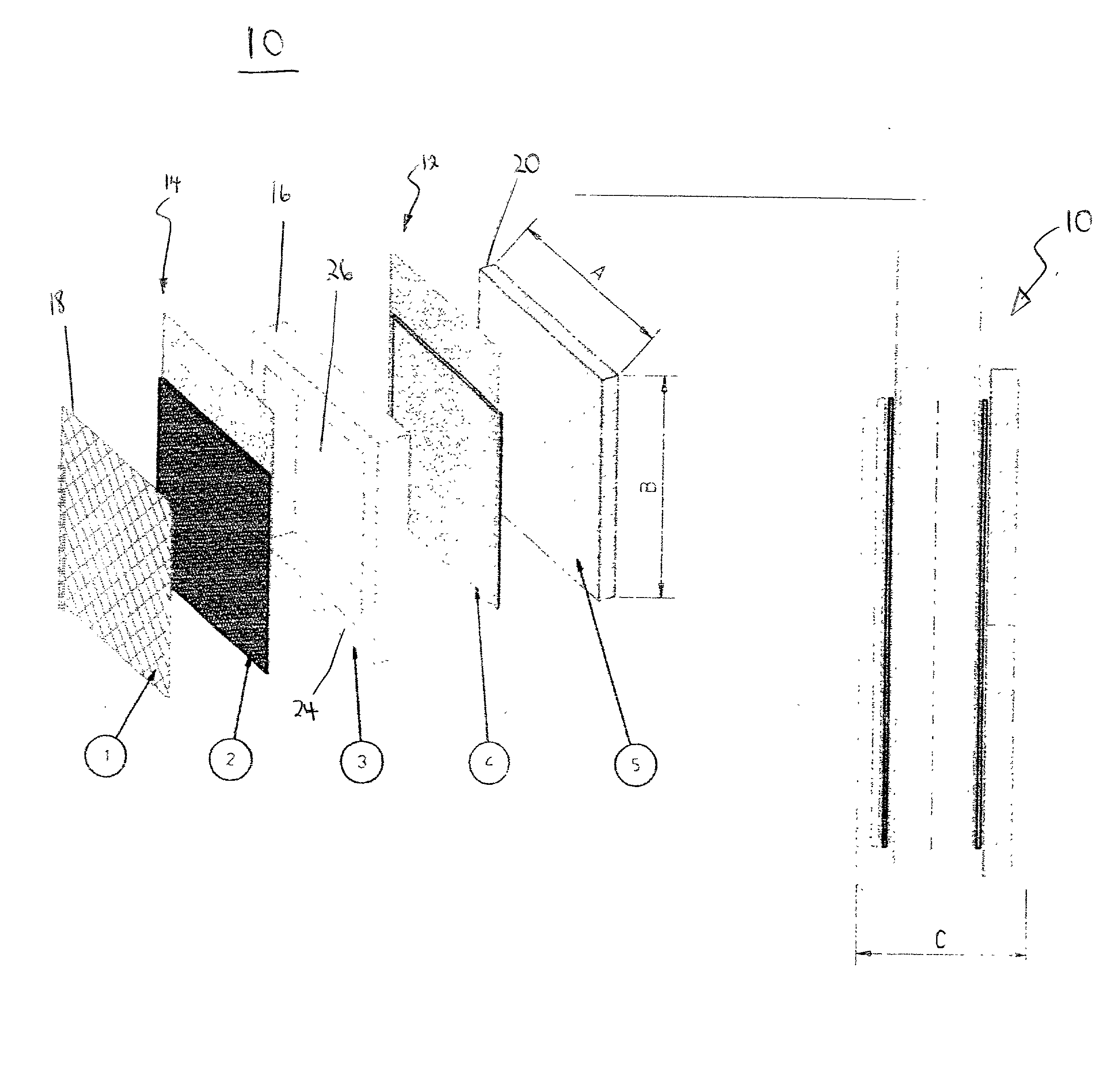
  • Direct liquid fuel cell and a novel binary electrode therefor
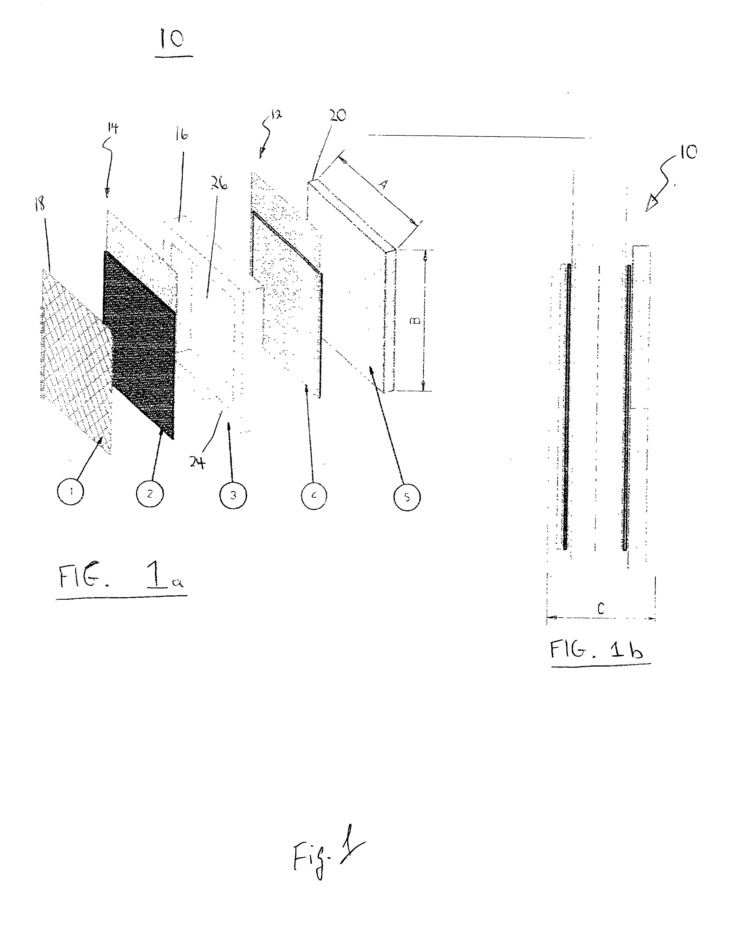
  • Direct liquid fuel cell and a novel binary electrode therefor
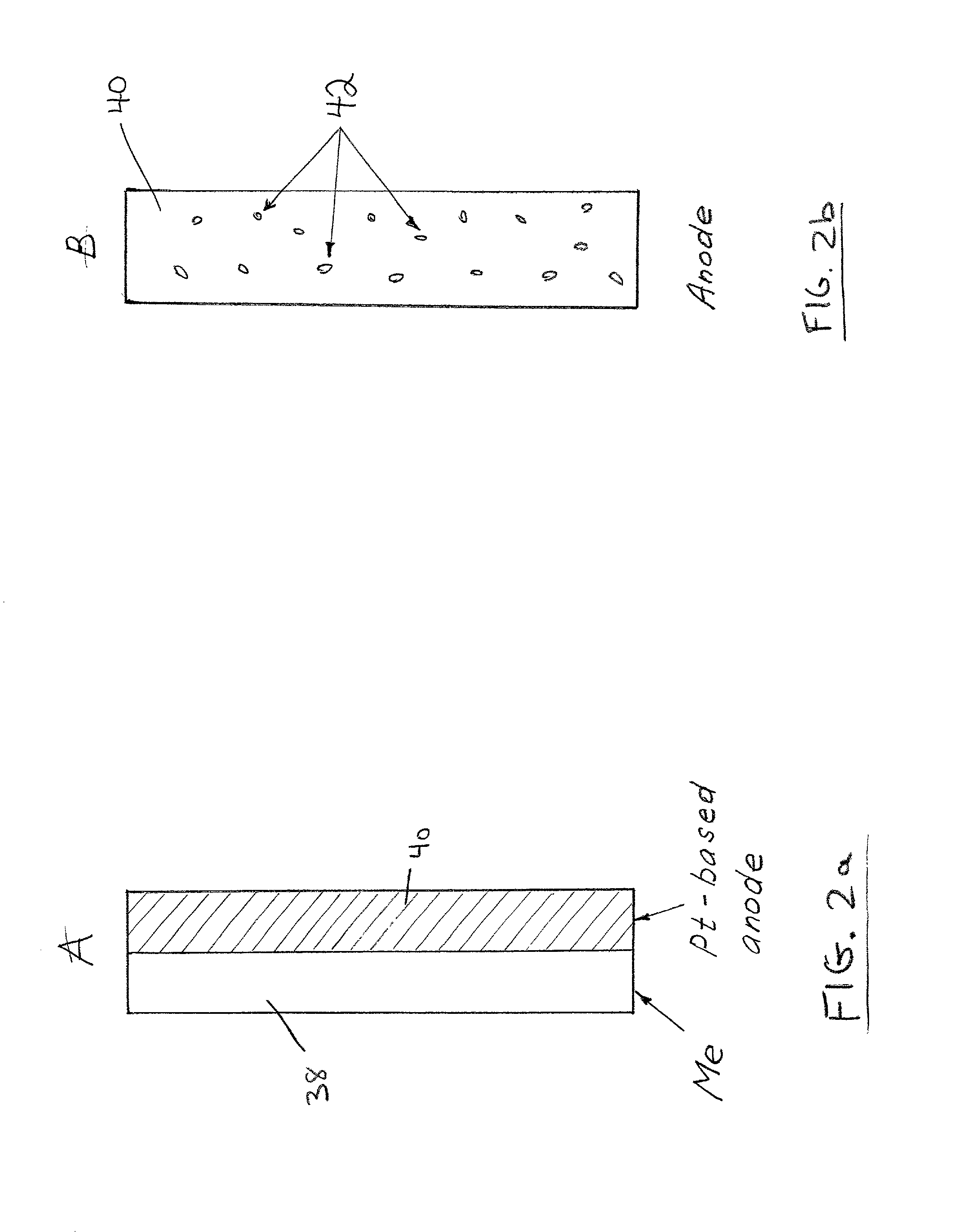
  • Direct liquid fuel cell and a novel binary electrode therefor

Examples


example 1

[0101] The fuel cell includes the cathode disclosed in a pending patent of the inventors (U.S. patent application Ser. No. 09 / 503,592) i.e., a Pt / Ru (1:1) catalyst, placed on a nickel mesh anode, and combined with an aluminum powder as a solid fuel source. The construction of the cell corresponds to FIG. 4a.

[0102] During the initial stage of the fuel cell discharge, when the value of the current exchange rate for the oxidation of methanol is significantly larger than that of Al oxidation (I.sub.0.sup.CH.sup..sub.3-.sup.OH>>I.sub.0.sup.Al), the actual current density of a cell is completely defined by the oxidation of methanol. As the formation of CO (Reaction 4) on the catalytically-active surface of the anode increases, the current exchange rate for the oxidation of methanol gradually decreases, until reaching the condition in which I.sub.0.sup.CH.sup..sub.-3.sup.OH<<I.sub.0.sup.Al. At this point, the overall current density of the fuel cell is defined, approximately, by k.sub.0.su...

example 2

[0108] The fuel cell includes the cathode disclosed in a pending patent of the inventors (U.S. patent application Ser. No. 09 / 503,592) i.e., a Pt / Ru (1:1) catalyst, placed on a nickel mesh anode, and combined with an aluminum powder as a solid fuel source. The construction of the cell corresponds to FIG. 4b.

[0109] The processes in the cell are substantially identical to those described in Example 1.

[0110] The theoretical capacity of the binary electrode is 1.5 Ah / g. The experimental cell provided a measured capacity of 0.9-0.95 Ah / g.


PUM


Abstract

A fuel cell comprising: (a) a binary anode, (b) a cathode, and (c) a liquid electrolyte disposed between and interacting with the binary anode and the cathode, wherein the binary anode includes at least one liquid fuel and at least one solid fuel. Preferably, the electrolyte includes an alcohol such as methanol, and the solid fuel includes aluminum, magnesium and / or zinc.

Description

FIELD AND BACKGROUND OF THE INVENTION[0001] The present invention relates to a binary electrode for a direct methanol fuel cell and a portable fuel cell based on such a binary electrode.[0002] Fuel cells based on oxygen reduction and hydrogen oxidation are well known for at least 100 years [V. Plzak, B. Rohland, and H. Wendt, "Fuel Cell Systems and Their Technical Maturity" Modern Aspects of Electrochemistry (Ed. B. Conway and J. O. M. Bokris), Vol. 26, pp. 147-161, 1990; G. Iwasita-Vielstich, "Progress in the Study of Methanol Oxidation", Advances in Electrochemical Science and Engineering (Ed. H. Gerischer and C. W. Tolias), pp. 127-170, 1990]. Modern H.sub.2 / O.sub.2 systems are well developed and can provide high power parameters.[0003] Nevertheless, the hazardous components along with the bulky and heavy equipment required for this type of fuel cell have led to the use of various other types of fuel, and more specifically, to the use of aqueous solutions of organic alcohols and ...

Claims


Application Information

Patent Timeline
IPC IPC(8): H01M4/02H01M4/86H01M8/04H01M8/10H01M12/06
CPCH01M4/02H01M4/8605H01M8/04H01M8/1004Y02E60/522H01M12/06H01M2004/024Y02E60/523H01M8/1009Y02E60/10Y02E60/50
Inventor FINKELSHTAIN, GENNADIBOROVSKY, GERSHONFILANOVSKY, BORISKATZMAN, YURI
Owner MORE ENERGY
Learn More