
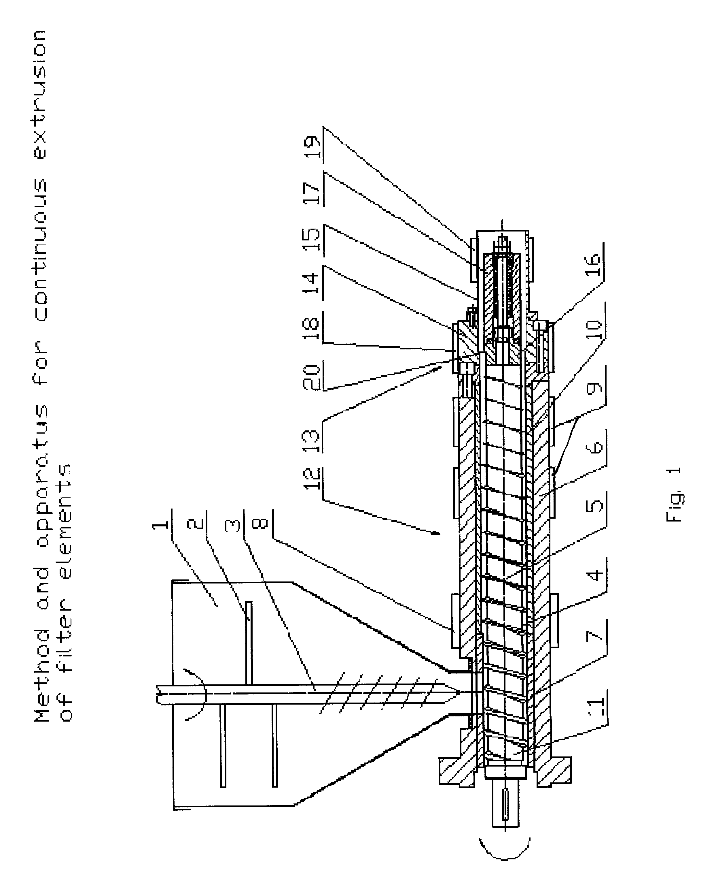
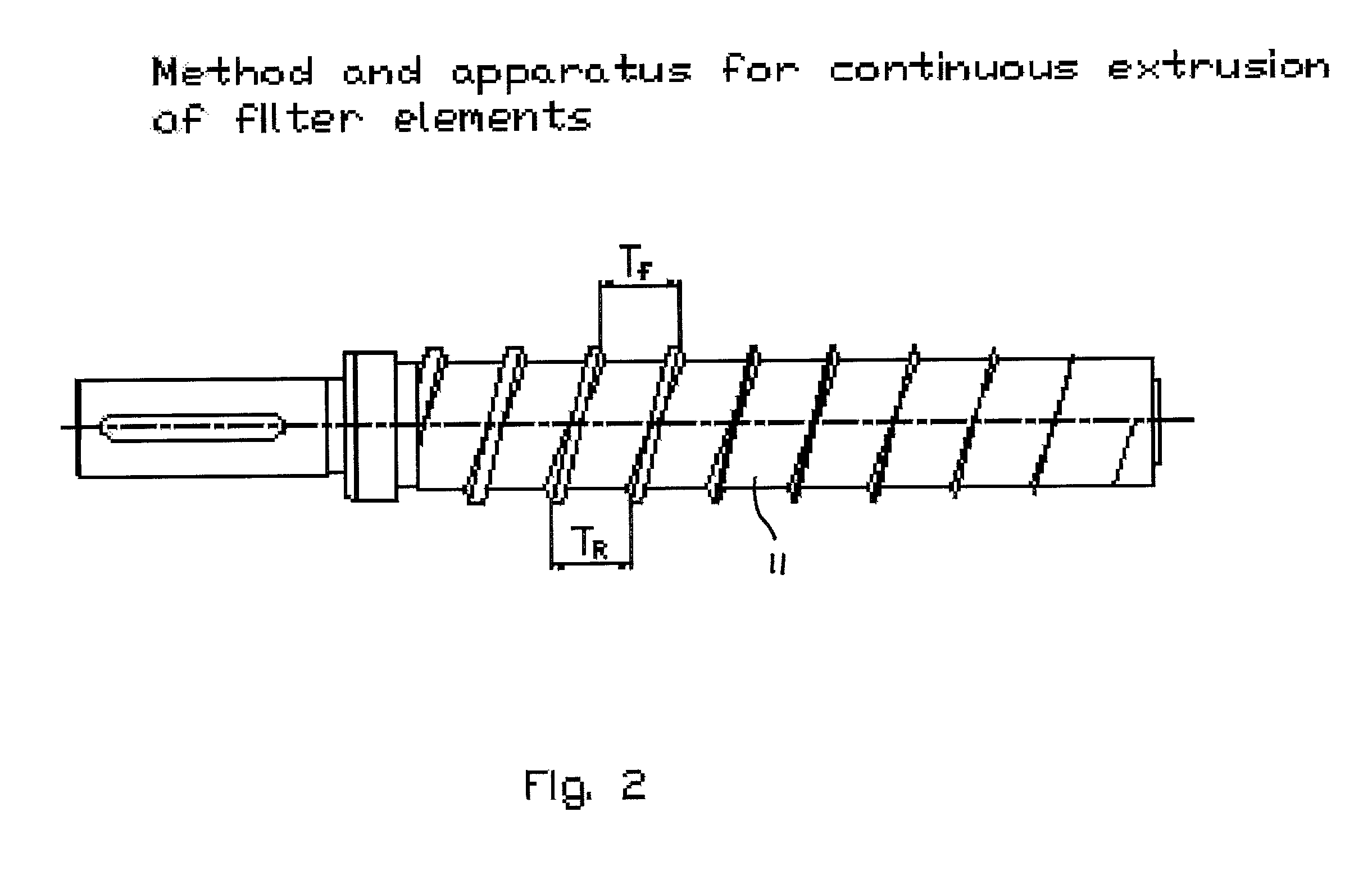
Method and apparatus for continuous extrusion of filter elements

a filter element and extruder technology, applied in auxillary shaping apparatus, butter manufacture, textiles and papermaking, etc., can solve the problems of inability to implement ordinary screws by polymer deformation, formation of over-compacted structures, lock-up of extruders, cavities and pores, etc., to achieve the effect of reducing the flight height of the screw, reducing the density of the porous structure, and reducing the flight heigh

Inactive Publication Date: 2002-05-30
BRUKOV NIKOLAY V +1
View PDF4 Cites 40 Cited by
  • Summary
  • Abstract
  • Description
  • Claims
  • Application Information

AI Technical Summary

Benefits of technology

[0010] The objectives of the invention include the technical advantages of producing a filter having longer service life and lower hydraulic resistance, while retaining high quality filtering properties and mechanical strength.
[0034] Difference in velocities of the screw and the mandrel make it possible to form the element with a porous structure wherein the thin layer adjacent to the surface of the mandrel contains a lower amount of the dust fraction which is formed due to grinding and wear off of the activated carbon components as compared to the result from the intensive rubbing against the surface of a mandrel which is rigidly connected to the screw and rotating at great angular velocity. This allows to prevent higher hydraulic resistance in the above described layer of the filter element.

Problems solved by technology

However, the mixtures that are used for obtaining porous activated carbon based filter elements contain so little amount of the polymer binder that compression, typical for ordinary screws can not be implemented by polymer deformation.
Therefore, the attempts to use standard extrusion machines to make porous filter elements have resulted in considerable destruction of the carbon component resulting in formation of over-compacted structures and lock up of the extruder.
The main problem in formation of products with homogeneous structure is the deterioration of material continuity in the course of shrinkage during cooling, so that cavities and pores develop.
However, the design elements of the traditional die, including using the braking, do not allow the use of a traditional die effectively to process the mixtures for making porous activated carbon block filter elements.
If the screw has constant depth and spacing of the spiral flights, local over-compaction of the extruded material due to delay or an obstacle to material movement, there may be material lock up.
The manufacture of products in the described extruder apparatus stipulated by the periodicity of the undertaken extrusion process does not allow to obtain products with uniform lengthwise density.
There is a lack of opportunity to control the product structure formation conditions due to inability to completely control friction in hydraulic joints.
When activated carbon is used as the active material, difficulties may arise, being caused by wedging of the material as the material moves from the barrel outlet to the extrusion head inlet.
One of the disadvantages of devices designed for the continuous extrusion of filter elements such as those disclosed in U.S. Pat. Nos. 5,189,092 and 5,249,948 is the uncontrollable braking axial force which develops as the material moves through the elongated extrusion head due to the location of the screw only in the cool zone, which hinders the ability to control the density of the porous structure of the filter elements (the main heaters are located in the extrusion head).
The performance of this type of extrusion apparatus is adversely affected because the material is still over-compacted due to the narrower helical flight channel extending from the loading zone to the extrusion head.
Consequently, these conditions provoke lock up of the mixture in the barrel and formation of hydraulically impervious zones in the filter elements.
Significant disadvantages of filter elements obtained in accordance with the above described prior art methods include insufficient service life and high hydraulic resistance.
Therefore, the desire to have porous material with homogeneous properties leads to lower filter life capacity and unjustified increase of the hydraulic resistance of the filter.

Method used


Image

  • Method and apparatus for continuous extrusion of filter elements
  • Method and apparatus for continuous extrusion of filter elements
  • Method and apparatus for continuous extrusion of filter elements

Examples


Embodiment Construction

[0036] 55 parts by weight of granular activated carbon (Calgon Carbon Corp., 80.times.235 mesh, USA) and 10 parts by weight of shredded polypropylene fiber (technical spun tread, 83.5 tex, Kurskkhimvolokno Co., Kursk, Russia, shredded, having fiber lengths to diameters ratio of about 10 to 15) are mixed in a turbulent four-blade mixer for 4 minutes at 500 rpm. The polypropylene fibers have a melting point of 160-170 degrees C. The fiber diameters range from about 10 to 20 microns, and their lengths are from about 200-1000 microns. These fibers have an MPI (Melt flow Index) of 1-5 gram / 10 minutes.

[0037] Then activated carbon fibers (fiber length to diameter ratio 10 to 15) in an amount of 10% of the weight of the granular activated carbon are added to the mixer. This corresponds to an activated carbon fiber to granular activated carbon ratio of 10:100 by weight, and the second stage of mixing is performed for 1 minute at 200 rpm. The activated carbon fibers are manufactured by Aquaph...


PUM

PropertyMeasurementUnit
melting pointaaaaaaaaaa
temperaturesaaaaaaaaaa

Abstract

A method and apparatus for making filter elements in which a mixture of activated carbon granules and fibers are processed with meltable polymer fibers to form a porous element. The density of the porous structure increases in a direction from the periphery thereof to its center. Also, the article formed by the method using the apparatus.

Description

[0001] This invention relates to the field of processing by extrusion. In particular, it relates to a method and apparatus for the continuous extrusion of porous, activated carbon block filter elements.[0002] Traditional extruders for polymeric material processing have had three zones: a) a loading zone with a cylindrical screw core and maximum helical flight height, b) a compression zone with a conical screw core, wherein the flight height is reduced, thereby effecting compression of the processed material, and c) a feed zone wherein the screw core is cylindrical and the flight height is minimum. Such design of the screw ensures intensive softening of the polymer material in the compression zone due to transition of mechanical energy to heat. However, the mixtures that are used for obtaining porous activated carbon based filter elements contain so little amount of the polymer binder that compression, typical for ordinary screws can not be implemented by polymer deformation. Therefo...

Claims


Application Information

Patent Timeline
Patent Type & Authority Applications(United States)
IPC IPC(8): B01D39/20B01D53/02B29C48/12B29C48/15B29C48/39B29C48/395B29C48/53
CPCB01D39/2062B29C47/369B01D53/02B01D2239/064B01D2239/086B01D2239/10B01D2253/102B29C47/003B29C47/0042B29C47/02B29C47/38B29K2105/04B29K2707/04B29L2031/14B29C47/6018B01D39/2065B29C48/15B29C48/12B29C48/0012B29C48/39B29C48/395B29C48/53
Inventor BRUKOV, NIKOLAY V.SCHMIDT, JOSEPH L.
Owner BRUKOV NIKOLAY V
Learn More