Qualfication test method and circuit for a non-volatile memory

Inactive Publication Date: 2002-03-28
MACRONIX INT CO LTD
View PDF0 Cites 77 Cited by
  • Summary
  • Abstract
  • Description
  • Claims
  • Application Information

AI Technical Summary

Benefits of technology

0011] The invention uses the physical phenomena for an insulating trapping layer in the non-volatile memory and provides an effective testing method associate with an app

Problems solved by technology

If the programmed state of partial of the memory cells in the memory array does not remain, the memory array is judged to fail during its lifetime.

Method used


Image

  • Qualfication test method and circuit for a non-volatile memory
  • Qualfication test method and circuit for a non-volatile memory
  • Qualfication test method and circuit for a non-volatile memory

Examples


Embodiment Construction

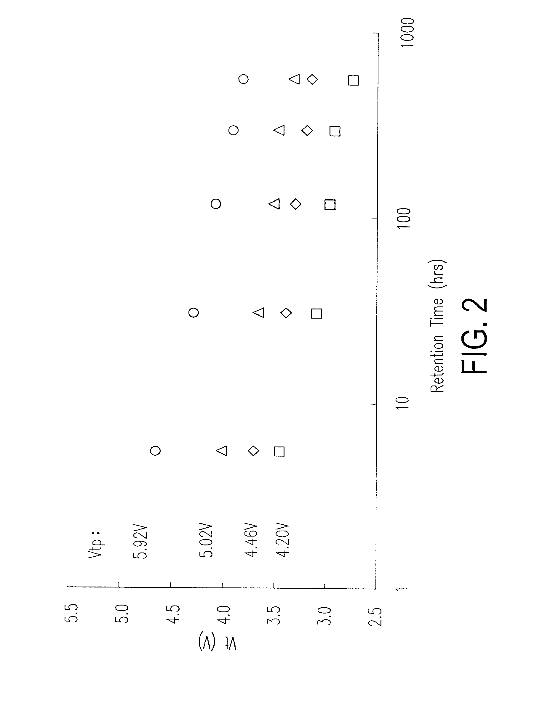
[0023] First, FIG. 2 are the relation curves for the threshold voltage Vt versus the retention time, under several programming voltages (Vtpgm, or Vtp), according to one preferred embodiment of this invention. In FIG. 2, for example, if the Vtp is at 5.92 V, then the threshold voltage Vt would vary from about 4.75 V to about 3.75 V as the retention time varies from 8 hours to 900 hours. According to FIG. 2, it is easily seen that the varying relation of the threshold voltage Vt and the retention time is a logarithmic relation and is about linear proportion. As the retention time get longer, the threshold voltage get smaller.

[0024] Taking FIG. 2 as an example, the threshold voltage (Vt) reduction rate is insensitive to Vtpgm, e.g. 1 V t log ( t ) 0.14 dV tpgm .

[0025] In other words, under the same failure criteria, for example, using Vt=2.5 V as a standard for failure judgment, when the programming voltage Vtp is higher, the corresponding lifetime gets shorter. The failure criteria i...


PUM


Abstract

A qualification test method for a non-volatile memory includes determining a relation curve between the programming voltage and the lifetime of the memory cell. A programming voltage with respect to the memory array within the expected lifetime is estimated. According to the relation curve, the accelerating test voltage and the test time period corresponding to the programming voltage operated in the expected lifetime are computed out. The test is performed for the test time period under the accelerating test voltage. All the memory cells at the programmed state are tested to see if the original programmed state still remains. If the programmed state remains, the memory array is judged to have the life period. If the programmed state does not remain, the memory array is judged to have no the life period.

Description

CROSS-REFERENCE TO RELATED APPLICATION[0001] This application claims the priority benefit of Taiwan application Ser. no. 90118850, filed Aug. 2, 2001.BACKGROUND OF THE INVENTION[0002] 1. Field of Invention[0003] The present invention relates to a test circuit and method for a non-volatile memory. More particularly, the present invention relates to a qualification test method and circuit for a non-volatile memory with a trapping layer.[0004] 2. Description of Related Art[0005] The non-volatile memory, such as flash EEPROM, usually has the gate structure with a control gate and a floating gate. The control gate is used to receive the activating control voltage of the memory cell, and the floating gate is used to store charges. In this structure, since the floating gate is usually a conductive body made of polysilicon, when the memory cell is programmed, the injected electrons to the floating gate would be distributed uniformly in the floating gate. Therefore, this kind of memory cell ...

Claims


Application Information

Patent Timeline
IPC IPC(8): G11C29/50
CPCG11C16/04G11C29/50G11C29/50004
Inventor TSAI, WEN-JERZOUS, NIAN-KAIWANG, TA-HUI
Owner MACRONIX INT CO LTD
Why Eureka
Try Eureka