
Microgrid troubleshooting method

Inactive Publication Date: 2016-06-23
NAT CHUNG SHAN INST SCI & TECH
View PDF1 Cites 1 Cited by
  • Summary
  • Abstract
  • Description
  • Claims
  • Application Information

AI Technical Summary

Benefits of technology

The present invention is a method for testing the strength and waveform of the short-circuit current in a renewable energy-based microgrid, and ensuring that conventional circuit breakers are capable of quarantining the troubles. The method allows for checking whether the path of the short-circuit current causes any anomaly to a related apparatus, such as a screw or a terminal plate. The overall security and performance indicators of the microgrid can be effectively tested with this method.

Problems solved by technology

Important considerations given to the design process include: the troubleshooting process causes an abnormal increase in the anode voltage of the DC system, causes the system's zero potential to shift from the neutral point to the trouble point and distort the initial distribution of paired earth potentials, compromises the insulation of the apparatuses of the DC system to thereby produce the second trouble point, and thus causes a short-circuit trouble between the anode and the cathode.
The aforesaid abnormal increase in the anode voltage of the DC system is likely to cause electric shock to the workers.
Furthermore, a trouble with the single-phase grounding of the AC system boosts the earth potential and thus causes damage to light-current apparatuses like a nearby communication apparatus and causes electric shock to the workers.

Method used


Image

  • Microgrid troubleshooting method
  • Microgrid troubleshooting method
  • Microgrid troubleshooting method

Examples


Embodiment Construction

[0018]The implementation of the present invention is described with a specific embodiment below. By referring to the disclosure contained in this specification, persons skilled in the art can easily gain insight into the other advantages and effects of the present invention.

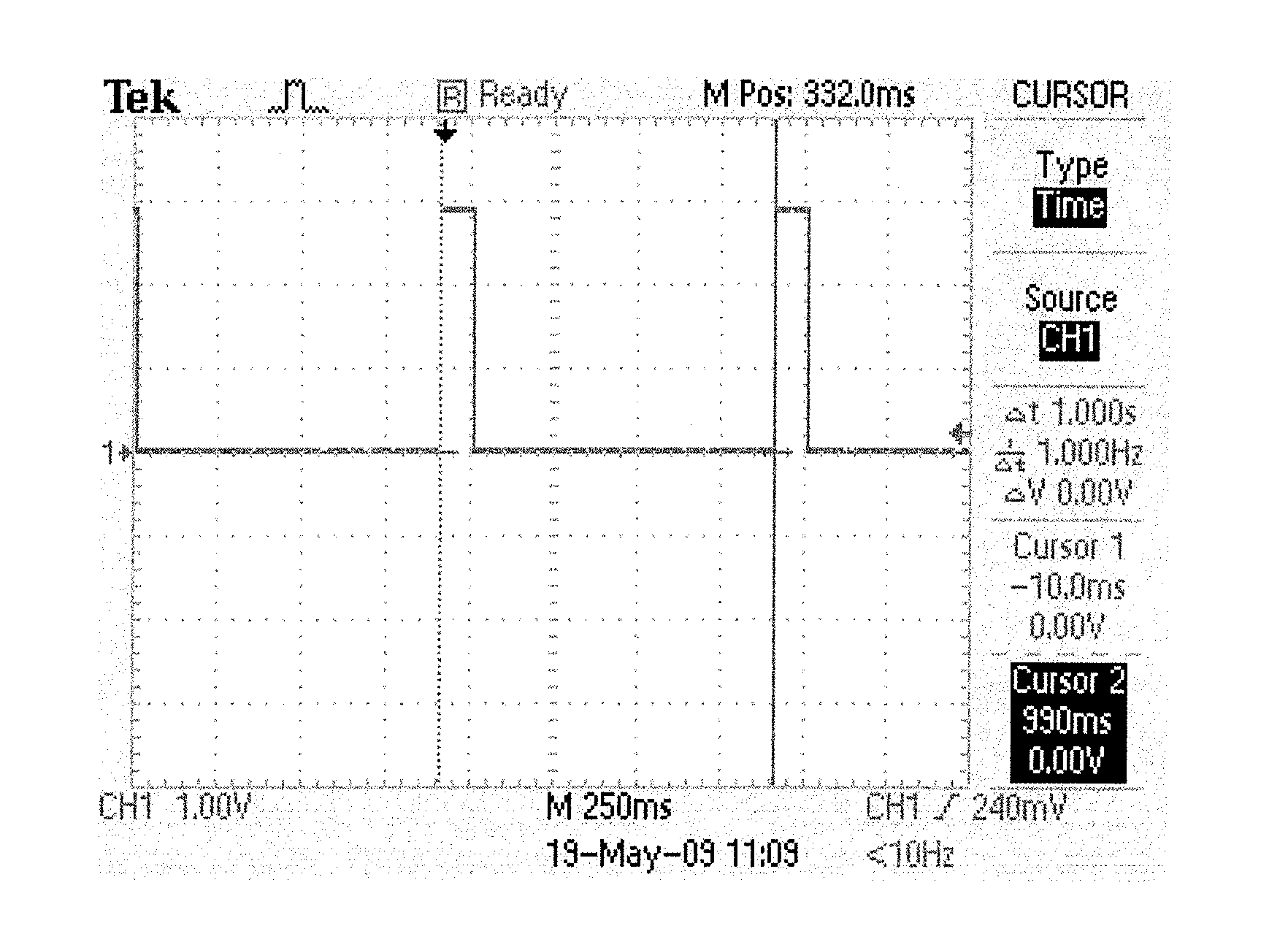
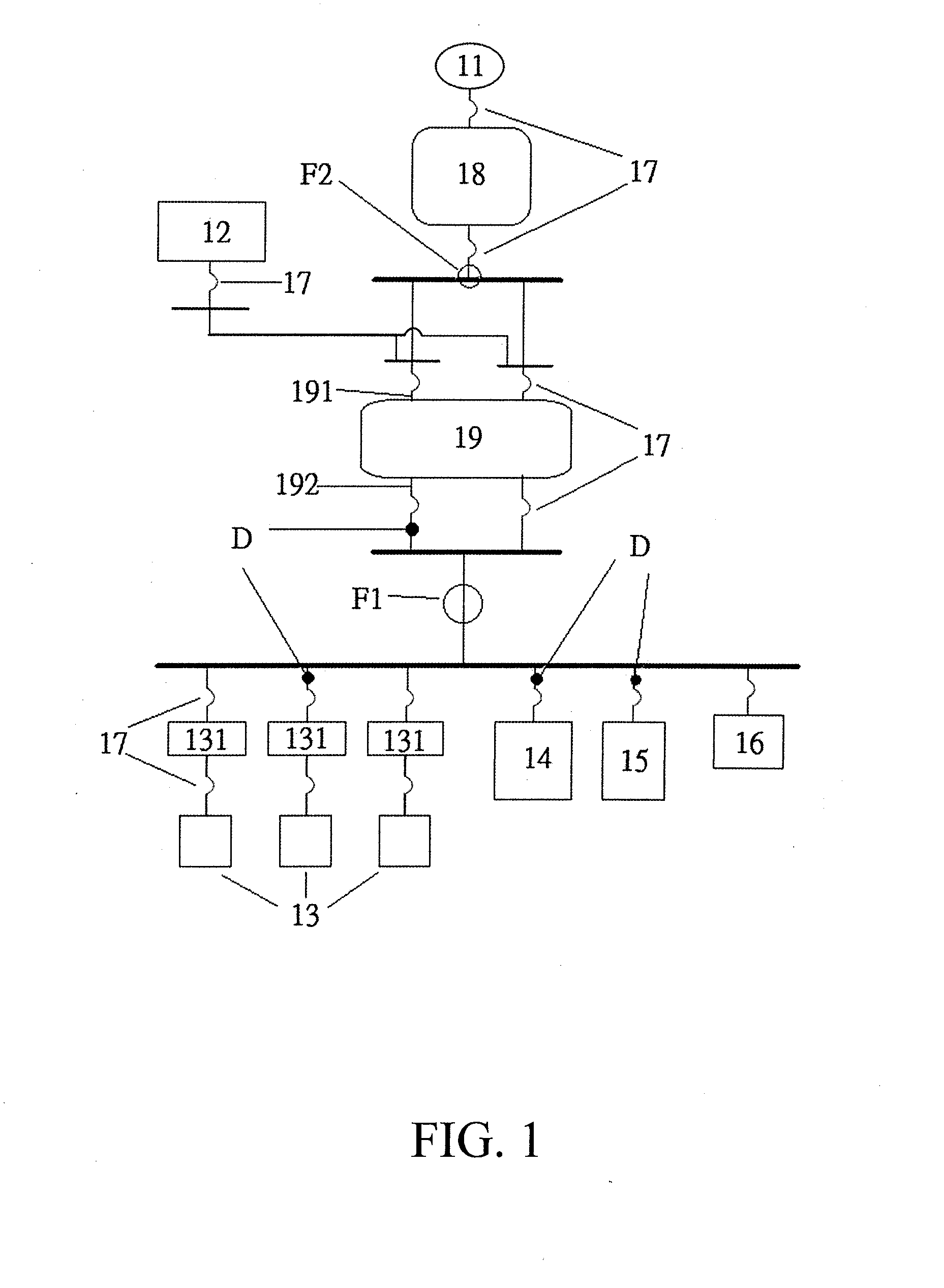
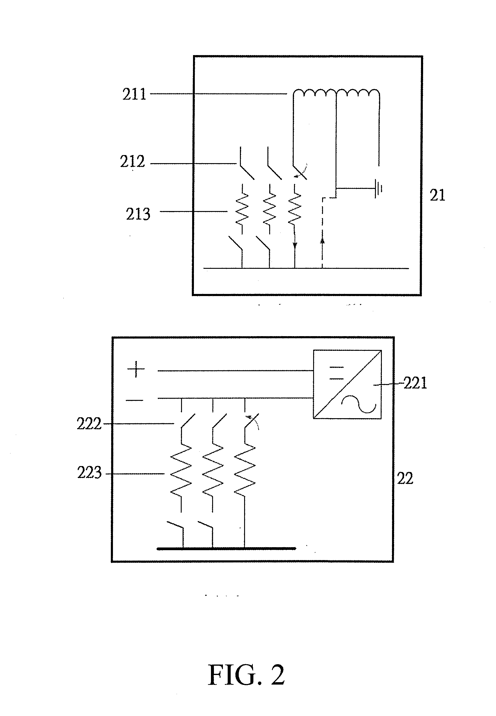
[0019]Referring to FIG. 1, there is shown a schematic view of the framework of a troubleshooting system according to an embodiment of the present invention. As shown in the diagram, the troubleshooting system comprises a utility electricity 11, an AC load 12, a solar power generating unit 13, an energy-storing unit 14, a fuel cell unit 15, a DC load 16, a plurality of protection units 17, a first trouble simulating unit 18, and a second trouble simulating unit 19. The first trouble simulating unit 18 is connected between the utility electricity 11 and the AC load 12. The second trouble simulating unit 19 has an AC end 191 and a DC end 192. The AC end 191 of the second trouble simulating unit 19 connects with the ...


PUM


Abstract

A microgrid troubleshooting method entails, connecting a first trouble simulating unit between a utility electricity and an AC load, wherein an AC end of a second trouble simulating unit connects with the AC load, and a DC end of the second trouble simulating unit connects with a solar power generating unit, an energy-storing unit, a fuel cell unit, and a DC load; switching the second trouble simulating unit to a short-circuit state, measuring a microgrid earth potential rise, short-circuit current of the solar power generating unit, and short-circuit current of the energy-storing unit, and checking whether the microgrid is damaged; and switching the first trouble simulating unit to a short-circuit state, measuring a microgrid earth potential rise, and checking whether the microgrid is damaged. The method is effective in simulating troubles with the microgrid, measuring the microgrid's short-circuit current, and testing whether the microgrid's protection mechanism is functioning well.

Description

FIELD OF TECHNOLOGY[0001]The present invention relates to electronic test technology, and more particularly, to a microgrid troubleshooting method for use with a renewable energy-based microgrid.BACKGROUND[0002]A microgrid consists of multiple renewable energy-based power generation systems. Although the renewable energy-based power generation system technology is sophisticated nowadays, the construction of a reliable microgrid system hinges on plenty of related techniques. A conventional DC microgrid mainly consists of distributed power sources, including: a solar power generating system (operating in conjunction with a maximum power point tracker (MPPT)), fuel cells, energy storing apparatuses (provided mostly in the form of lithium iron batteries), and inverters. To ensure that each part and component of the microgrid is functioning well, it is necessary to design a troubleshooting process flow method for evaluating whether the system comes with sufficient protective mechanisms, ...

Claims


Application Information

Patent Timeline
IPC IPC(8): G06F17/50
CPCG06F17/5009H02J2300/30H02J2300/20H02J3/381H02J3/0012H02J2300/22G06F30/20
Inventor CHEN, SHI-LINLIEN, KENG-YUJEN, KUO-KUANGHUANG, CHEN-HO
Owner NAT CHUNG SHAN INST SCI & TECH
Learn More