In-situ testing equipment for testing micromechanical properties of material in multi-load and multi-physical field coupled condition

Active Publication Date: 2016-07-28
JILIN UNIV
View PDF9 Cites 38 Cited by
  • Summary
  • Abstract
  • Description
  • Claims
  • Application Information

AI Technical Summary

Benefits of technology

The testing equipment described in this patent has a unique design that allows for the performance of various types of mechanical tests on test pieces using a single apparatus. The apparatus includes a three-point bending module, an impressing module, and a thermal field and magnetic field application module. The modules are interchangeably mounted on a common support plate, which saves space and increases the range of test options. The equipment also includes various components for in-situ observation and real-time dynamic observation of the test piece, which can aid in researching the microstructural profile of materials. The patent proposes new methods for developing solid materials, structural designs, manufacturing, life prediction, and reliability assessment.

Problems solved by technology

However, such tests are usually offsite tests, which cannot provide a real-time dynamic observation of microstructural profiles of a test piece during the tests.
Thus, the inner mechanism of microstructural changes and macromechanical properties of a material cannot be effectively combined to characterize the performance of the material.
Mechanical property test in a single load manner cannot accurately reflect the loads applied on material and component in an actual situation, that is, no accurate evaluation can be made on mechanical properties of a material under action of complex load.
Another way of applying complex load is accomplished by utilizing a complicated and expensive multifunctional material testing machine.
However, such a testing machine can only apply certain type of complex load, two or more loads cannot be separately or successively applied, such that no accurate evaluation can be made on mechanical properties of a material and its product and inner mechanism of deformation and damage under the action of complex load, and thus popularization and application of material testing machine are significantly restrained.
Existing commercial testing machine can seldom fulfill the requirements of simulation and testing of properties of a material in the above-described multi-physical field.

Method used


Image

  • In-situ testing equipment for testing micromechanical properties of material in multi-load and multi-physical field coupled condition
  • In-situ testing equipment for testing micromechanical properties of material in multi-load and multi-physical field coupled condition
  • In-situ testing equipment for testing micromechanical properties of material in multi-load and multi-physical field coupled condition

Examples


Embodiment Construction

[0142]Details and specific embodiments of the invention will be described in conjunction with the accompanying drawings.

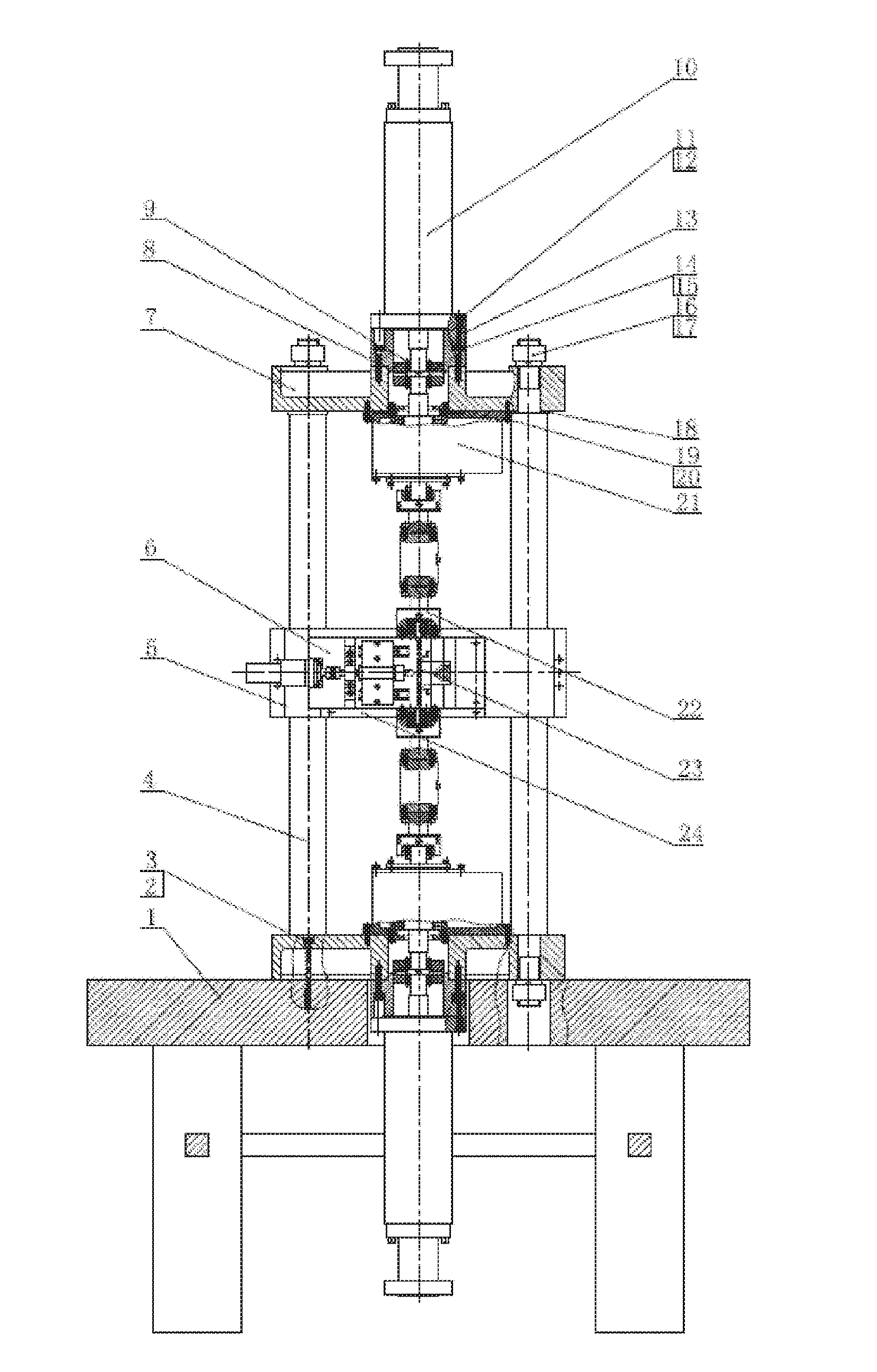
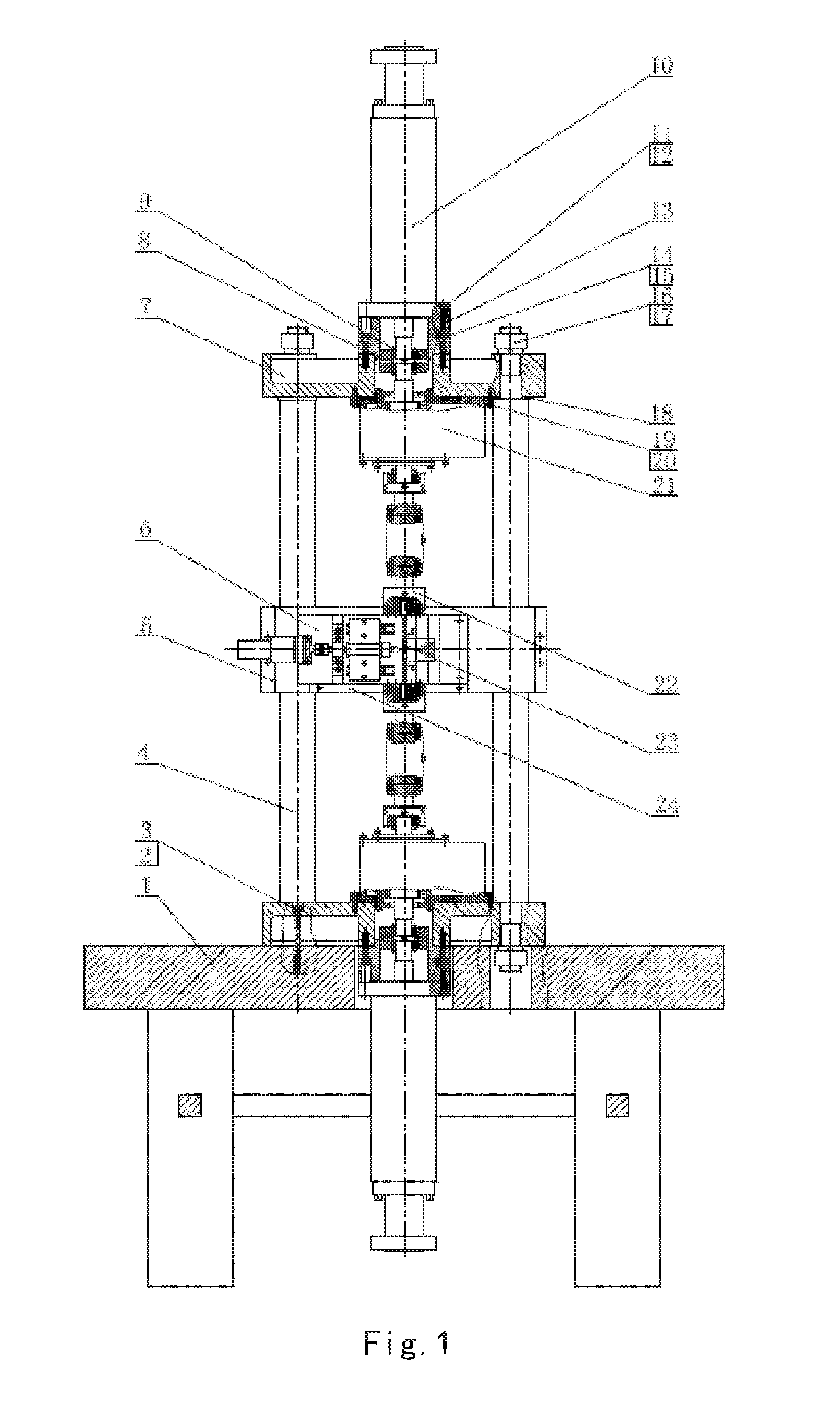
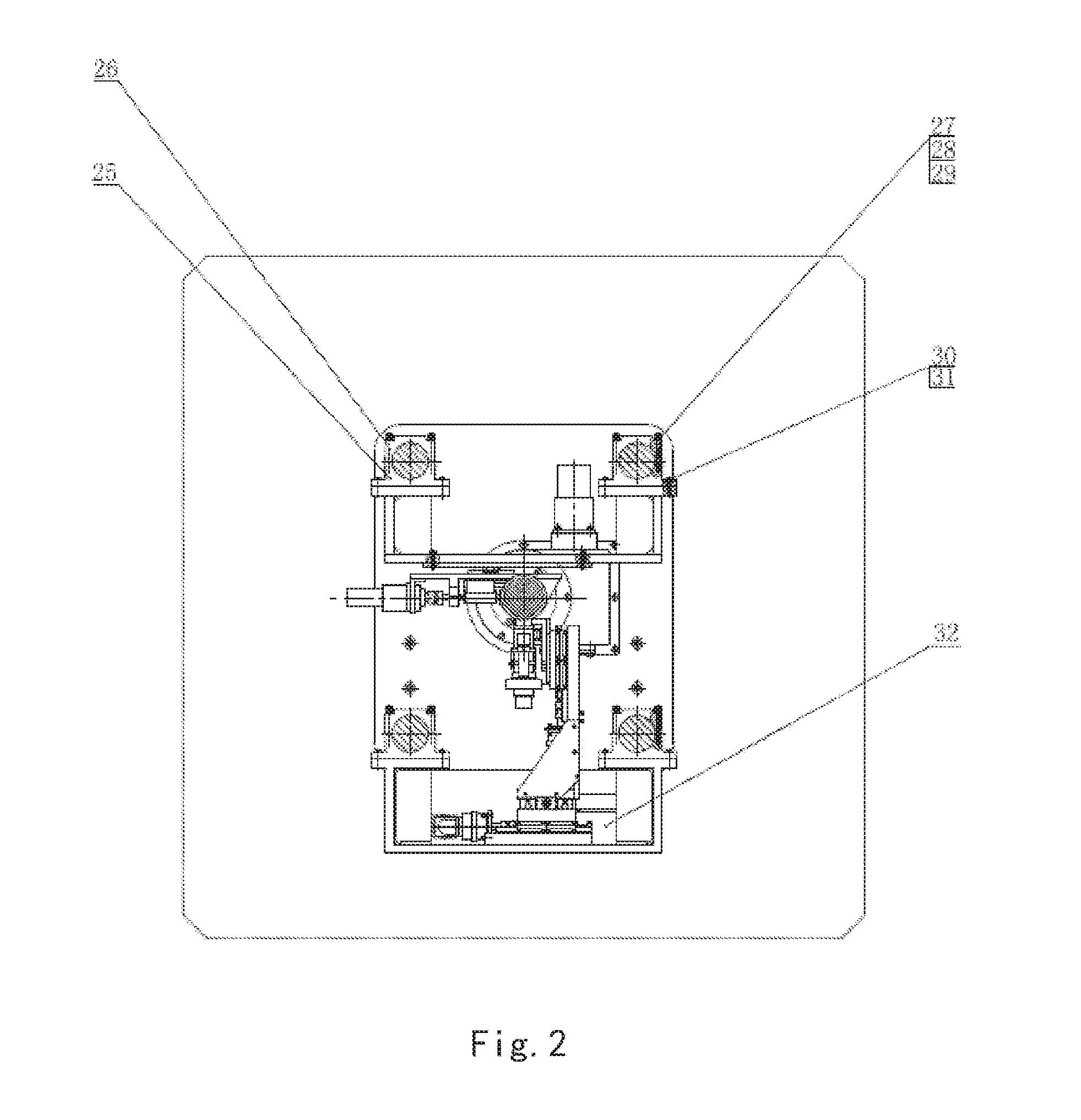
[0143]Referring to FIG. 1 to FIG. 11, an in-situ testing equipment according to an embodiment of the invention, which is configured for testing micromechanical properties of material in a multi-load and multi-physical field coupled condition, and comprises a frame supporting module, a tension / compression-low cycle fatigue module, a torsioning module 21, a three-point bending module 6, an impressing module 33, a thermal field and magnetic field application module 34, an in-situ observation module 32 and a clamp body module. The frame supporting module provides a structure support for the whole testing equipment; the tension / compression-low cycle fatigue module is arranged at upper and lower ends of the testing equipment, the torsioning module 21 is directly arranged at a front end of the tension / compression-low cycle fatigue module; the three-point bending module 6,...


PUM


Abstract

An in-situ testing equipment for testing micromechanical properties of a material in a multi-load and multi-physical field coupled condition is disclosed. The equipment comprises a frame supporting module, a tension / compression-low cycle fatigue module, a torsioning module (21), a three-point bending module (6), an impressing module (33), a thermal field and magnetic field application module (34), an in-situ observation module (32) and a clamp body module (22). The frame supporting module provides a structural support for the whole testing equipment, the tension / compression-low cycle fatigue module is arranged at upper and lower ends of the testing equipment, the torsioning module (21) is directly arranged at a front end of the tension / compression-low cycle fatigue module, the three-point bending module (6), the impressing module (33) and the thermal field and magnetic field application module (34) are disposed on a support post at one side of the whole testing equipment through a common replacing component, and the in-situ observation module is disposed on another support post at the other side of the testing equipment. The clamp body module is connected to a front segment of the torsioning module, so as to clamp a test piece. An overall structure of the testing equipment is configured in a vertically symmetrical arrangement achieved by using four support posts. Two identical servo hydraulic cylinders (10) and two torsioning modules (21) are located at the upper and the lower ends of the testing equipment respectively and are used to perform a symmetrical tension / compression test and a symmetrical torsion test on the test piece (23) positioned centrally. The testing equipment is capable of realizing applications of five different types of loads including tension / compression, low cycle fatigue, torsion, bending and impressing, performing an intensive study on micromechanical properties of the material in the multi-load and multi-physical field coupled condition by using built-in electric, thermal and magnetic application modules and the in-situ observation module, and acquiring relations between deformation behavior, mechanism of damage, performance weakening of the material, applied loads and material properties.

Description

TECHNICAL FIELD[0001]Embodiments of the present application relate to field of mechanical test of materials, particularly, to a testing equipment for testing micromechanical properties of materials, and more particularly, to an in-situ testing equipment for testing micromechanical properties of materials in a multi-load and multi-physical field coupled condition. The equipment may apply a single load selected from a group consisted of tension / compression, low cycle fatigue, torsion, bending and impressing, or a combination of two or more loads selected from the group simultaneously to the material to be tested. The equipment may also perform a test on a functional material, such as a ferromagnetic material, a thermomagnetic material, a semiconductive material, etc. in a multi-physical field coupled condition formed by a temperature field, an electric field, a magnetic field and a stress field. With an in-situ observation module, such testing equipment may perform a real time and dyn...

Claims


Application Information

Patent Timeline
IPC IPC(8): G01N3/06G01N3/22G01N3/20G01N3/08
CPCG01N3/06G01N3/20G01N3/22G01N3/08G01N3/04G01N3/26G01N3/32
Inventor ZHAO, HONGWEIREN, LUQUANLI, JIANPINGHUANG, HUZHANG, PANFENGHU, XIAOLICHENG, HONGBINGFANG, DAININGMA, ZHICHAOZHUANG, QINGWEIGAO, JINGDONG, XIAOLONGTANG, KEHONGZHANG, FUZOU, QINGZHU, YUXIANGDONG, JINGSHIFAN, ZUNQIANGHU, YONGSHANG, TAO
Owner JILIN UNIV
Why Eureka
Try Eureka