
Magnetic recording medium and magnetic recording apparatus

a recording medium and magnetic recording technology, applied in special recording techniques, instruments, record information storage, etc., can solve the problems of difficult control of crystallographic orientation, difficult to cope with such situation with existent media, and the noise of the medium has to be reduced further

Inactive Publication Date: 2002-02-14
HITACHI GLOBAL STORAGE TECH JAPAN LTD
View PDF4 Cites 26 Cited by
  • Summary
  • Abstract
  • Description
  • Claims
  • Application Information

AI Technical Summary

Problems solved by technology

On the other hand, in the glass substrate, it is difficult for the control of crystallographic orientation since there are a lot of (110) oriented components when the underlayer is merely formed directly on the substrate.
For attaining super-high density recording of 10 Gbits of more per one square inch, it is difficult to cope with such situation with existent media and medium noises have to be reduced further.
In view of the basic application uses of magnetic recording media of preserving information, this is an important problem (defect) and this subject has to be overcome soon.
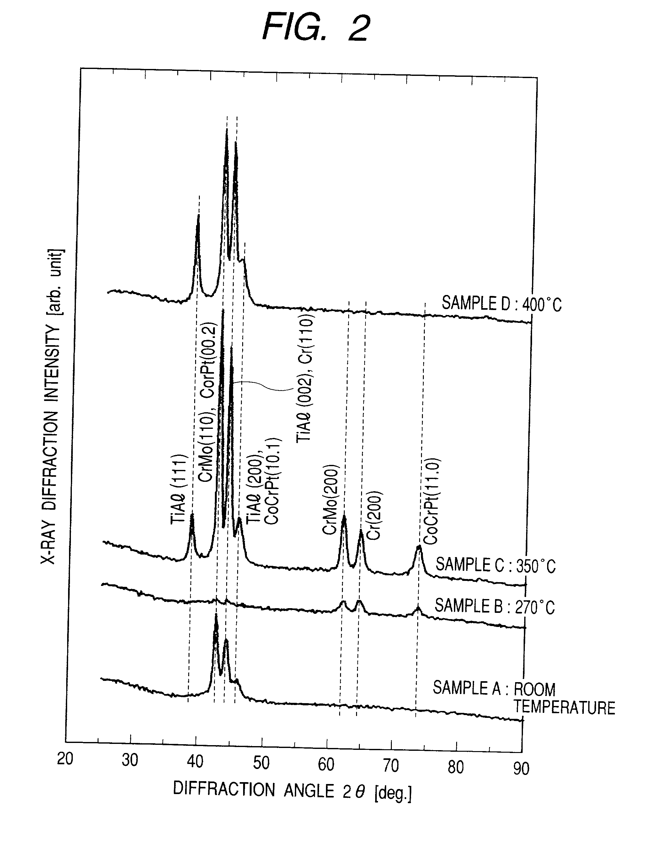
However, when a thin film is prepared by sputtering at Ti:Al=1:1 composition, it has been found that there are film deposition conditions not causing crystallization depending on the substrate temperature.

Method used


Image

  • Magnetic recording medium and magnetic recording apparatus
  • Magnetic recording medium and magnetic recording apparatus
  • Magnetic recording medium and magnetic recording apparatus

Examples


example 2

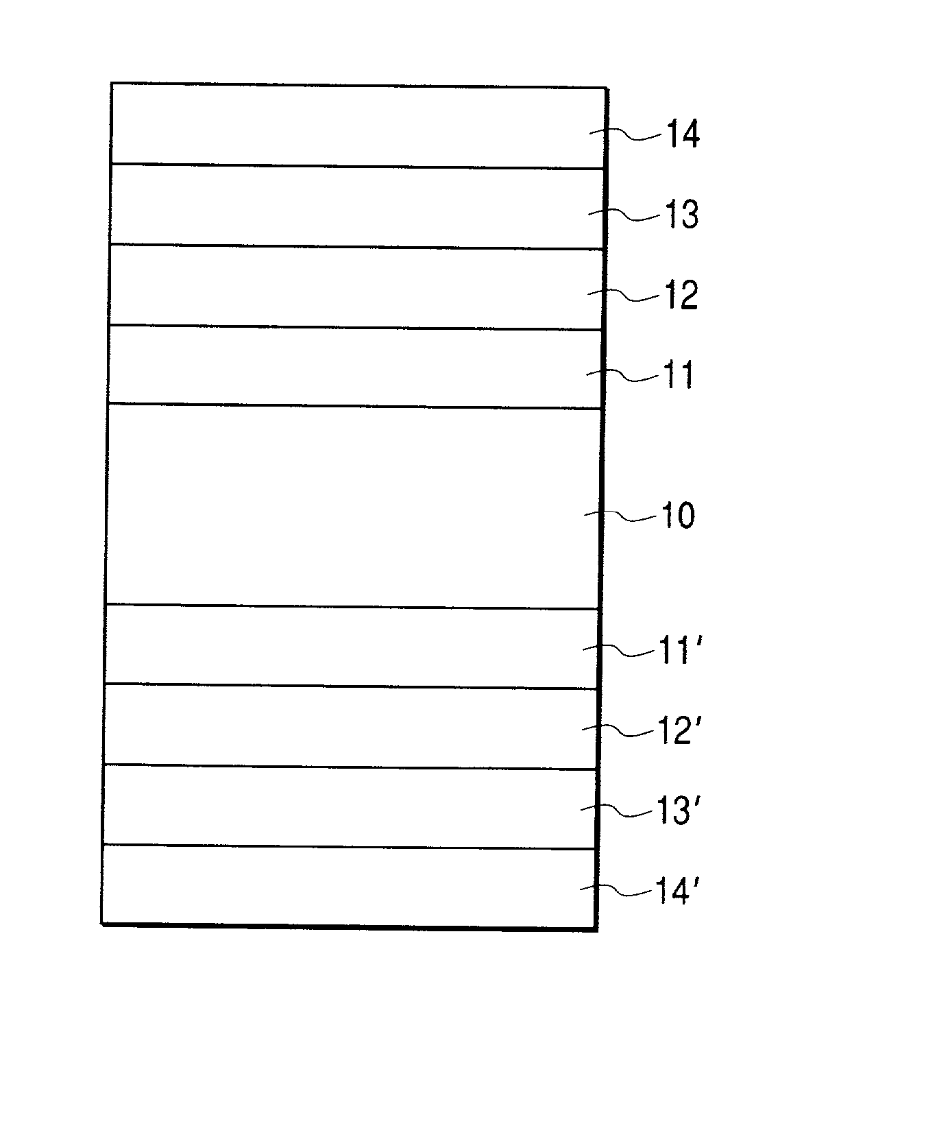
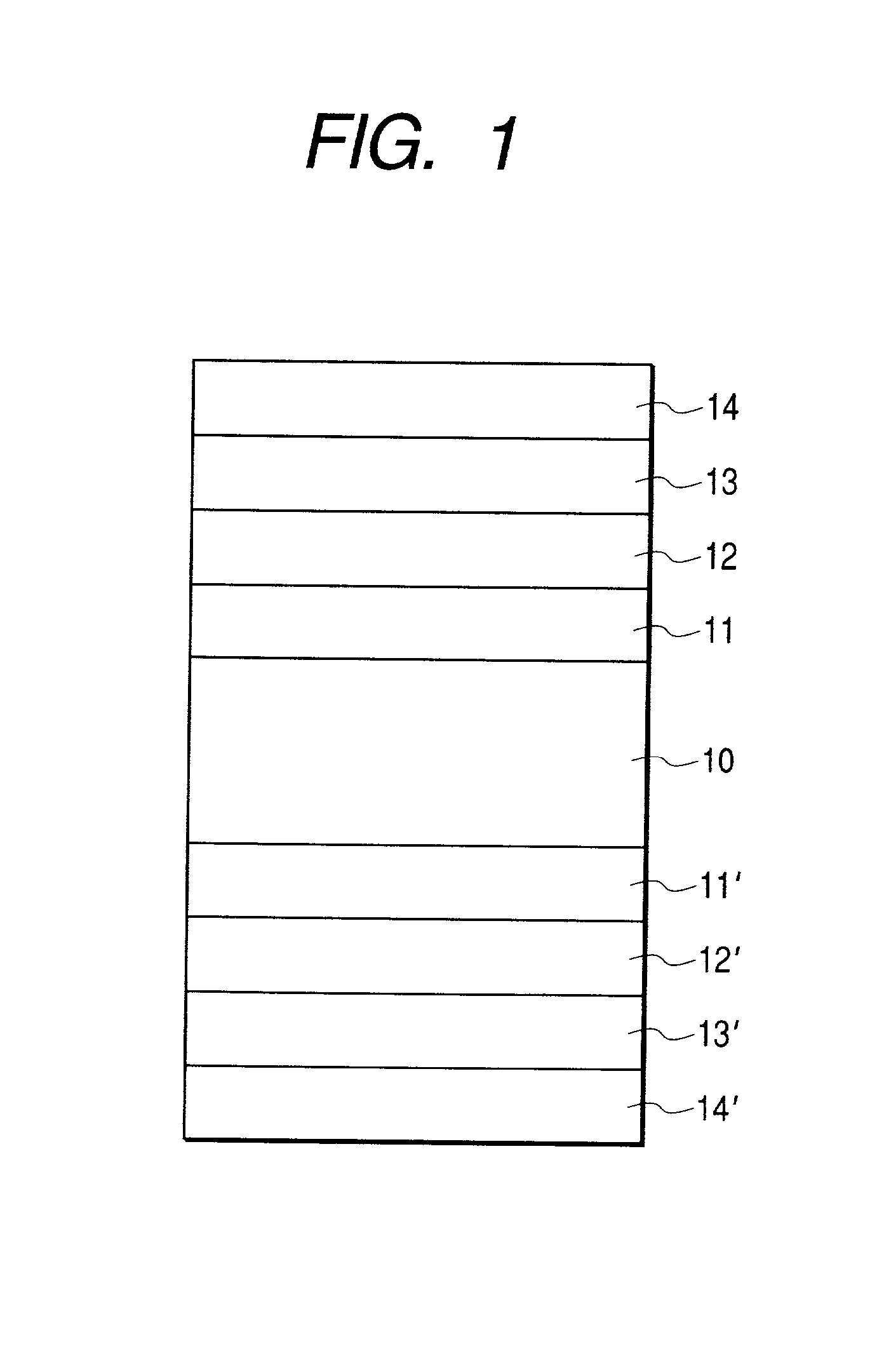
[0058] The medium prepared in accordance with this example is to be explained with reference to FIG. 1. On a glass substrate 10 of 65 mm.phi. in outer diameter, TiAl seed layers 11, 11' (20 nm) were formed. Then, Cr-20 at % Ti underlayers 12, 12' (20 nm) were formed, and Co system alloy magnetic layers 13, 13' (13 nm) were disposed. Finally, protective layers 14, 14' each comprising C were formed and lubricants were coated to manufacture a magnetic recording medium of this example. In this example, all of the layers were prepared by a DC magnetron sputtering method. Basic sputtering conditions were at an Ar gas pressure of 0.27 Pa and an input power density of 39.5 kW / m.sup.2.

[0059] FIG. 6 shows the change of X-ray profiles when using Co-20 at % Cr-10 at % Pt (14 nm) for the magnetic layer and changing the heating conditions for TiAl under the substrate heating conditions of 270.degree. C..times.10 min. TiAl was not heated for the specimen K and the heating temperature for TiAl was ...

example 3

[0064] In this example, change of the medium characteristics was examined in a case of varying the compositional ratio of the TiAl seed layer. The medium prepared in this example is to be explained with reference to FIG. 1. On a glass substrate 10 of 65 mm.phi. in outer diameter, TiAl seed layers 11, 11' (20 nm) were formed. Then, dual underlayers 12, 12' each comprising a first underlayer of Cr-20 at % (15 nm) and a second underlayer of Cr-30 at % Mo (5 nm) were formed, and a magnetic layers 13, 13' of Co-21 at % Cr-16 at % Cr-16 at % Pt-5 at % Ta (15 nm) were disposed. Finally, protective layers 14, 14' comprising C were formed and lubricants were coated to prepare a magnetic recording medium of this example. In this example, all of the layers were prepared by a DC magnetron sputtering method. Basic sputtering conditions were at an Ar gas pressure of 0.27 Pa and an input power density of 39.5 Kw / m.sup.2. The substrate heating condition was at 270.degree. C..times.10 min. Further, ...

example 4

[0070] The performance of the magnetic recording media of the examples described above can be utilized fully by using a magnetic head having a read only sensor utilizing the magnetoresistive effect as exemplified in FIG. 9.

[0071] A recording magnetic head was an induction type thin film magnetic head comprising a pair of recording magnetic poles 90, 91, and coils 92 intersecting magnetically therewith in which the thickness of a gap layer between the recording magnetic poles was 0.25 .mu.m. Further, the magnetic pole 91 was paired with a magnetic shield layer 95 of 1 .mu.m thickness, which served also as a magnetic shield for the reading magnetic head, and the distance between the shield layers was 0.2 .mu.m. The read only magnetic head was a magnetoresistive head comprising a magnetoresistive sensor 93 and a conductor 94 as an electrode. The magnetic head was disposed on a magnetic head slider substrate 96. In FIG. 9, the gap layer between the recording magnetic poles, and the gap ...


PUM

PropertyMeasurementUnit
crystal grain sizeaaaaaaaaaa
grain sizeaaaaaaaaaa

Abstract

A magnetic recording apparatus of a large capacity capable of super-high density recording of 10 Gbits or more per one square inch has a magnetic recording medium prepared by forming a Co alloy magnetic layer by way of an underlayer comprising Co or Cr alloy on a substrate, in which an amorphous or micro crystal seed layer containing at least Ti and Al is disposed between the substrate and the underlayer, the magnetic layer has an h.c.p. structure and is grown to (1.1.0) direction parallel with the substrate, the magnetic recording medium of high coercivity and reduced noises and undergoing less effects of thermal fluctuation being provided because of in-plane orientation of the axis of easy magnetization of the magnetic layer and the reduced size of the magnetic crystal grains and dispersion thereof, combination of the magnetic recording medium and the magnetic head having a read only device utilizing the magnetoresistive effect capable of providing a magnetic recording apparatus having a recording density at 10 Gbits or more per one square inch.

Description

[0001] 1. Field of the Invention[0002] This invention concerns a magnetic recording medium such as a magnetic drum, a magnetic tape, a magnetic disk and a magnetic card, as well as a magnetic recording apparatus and, more in particular, it relates to an in-plane magnetic recording medium suitable to super-high density recording of 10 Gbits or more per one square inch and a magnetic recording apparatus using the magnetic recording medium described above.[0003] 2. Description of the Related Prior Art[0004] In recent years a demand has been increased more for hard disk drives with an aim of mounting on a notebook-sized personal computer. Since it is a basic premise that the notebook-sized personal computer is portable, a hard disk is required to have excellent impact resistance. Further, for a hard disk drive mounted on a disk array system, it has now been required to rotate a magnetic recording medium at a higher speed than usual with an aim of high speed transfer of data. For the med...

Claims


Application Information

Patent Timeline
Patent Type & Authority Applications(United States)
IPC IPC(8): G11B5/738G11B5/00G11B5/64G11B5/65G11B5/73G11B5/851
CPCG11B5/00G11B5/656G11B5/732G11B5/7325G11B2005/001G11B5/7379G11B5/7369G11B5/657
Inventor YAMAMOTO, TOMOOTAMAI, ICHIROTANAHASHI, KIWAMUISHIKAWA, AKIRA
Owner HITACHI GLOBAL STORAGE TECH JAPAN LTD
Learn More