
Electronic device and method for manufacturing electronic device

a technology of electronic devices and manufacturing methods, applied in the field of electronic devices, can solve problems such as the inability to solve the problem of increasing common differences

Active Publication Date: 2022-11-22
TPK ADVANCED SOLUTIONS
View PDF4 Cites 0 Cited by
  • Summary
  • Abstract
  • Description
  • Claims
  • Application Information

AI Technical Summary

Benefits of technology

This patent is about a new method for making electronic devices using a very thin and flexible material. The method improves the problem of differences in the bonding area that can occur when the length of the area increases. The method also improves the accuracy of the bonding.

Problems solved by technology

However, with the development of ultra-thin flexible substrate technology, it is impossible to solve the problem of increasing common difference as the length of the bonding area in the product increases.

Method used

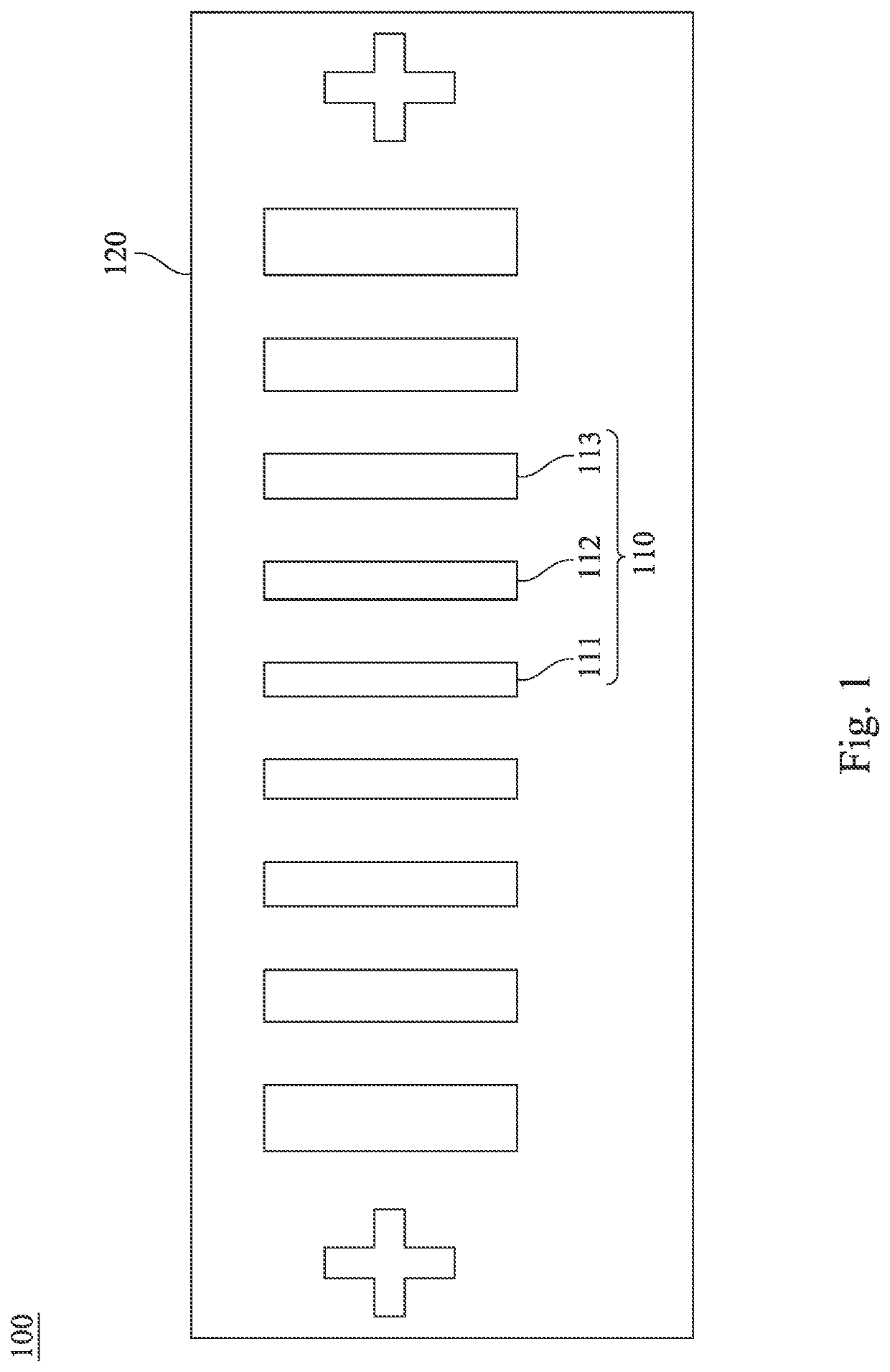
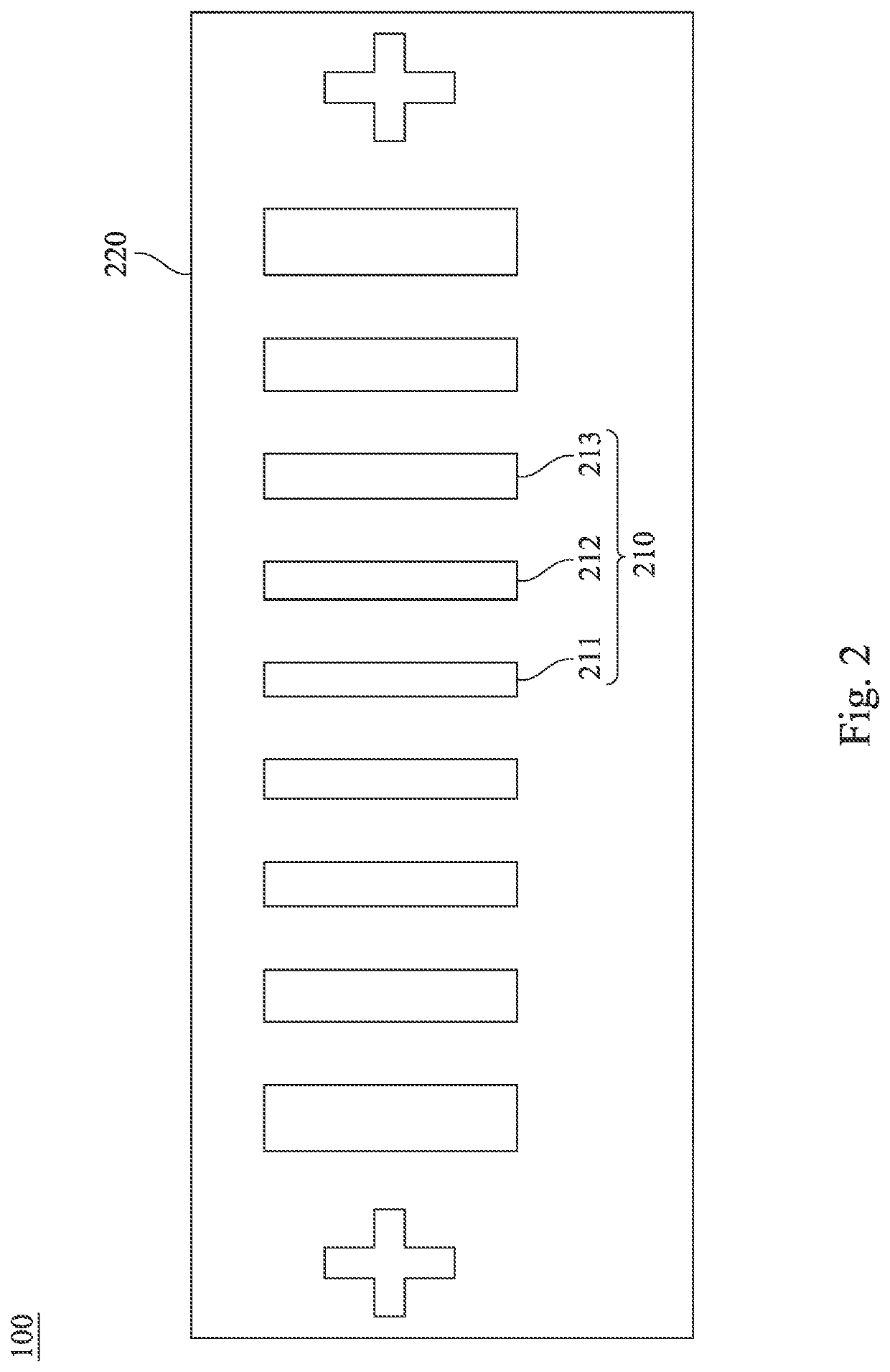
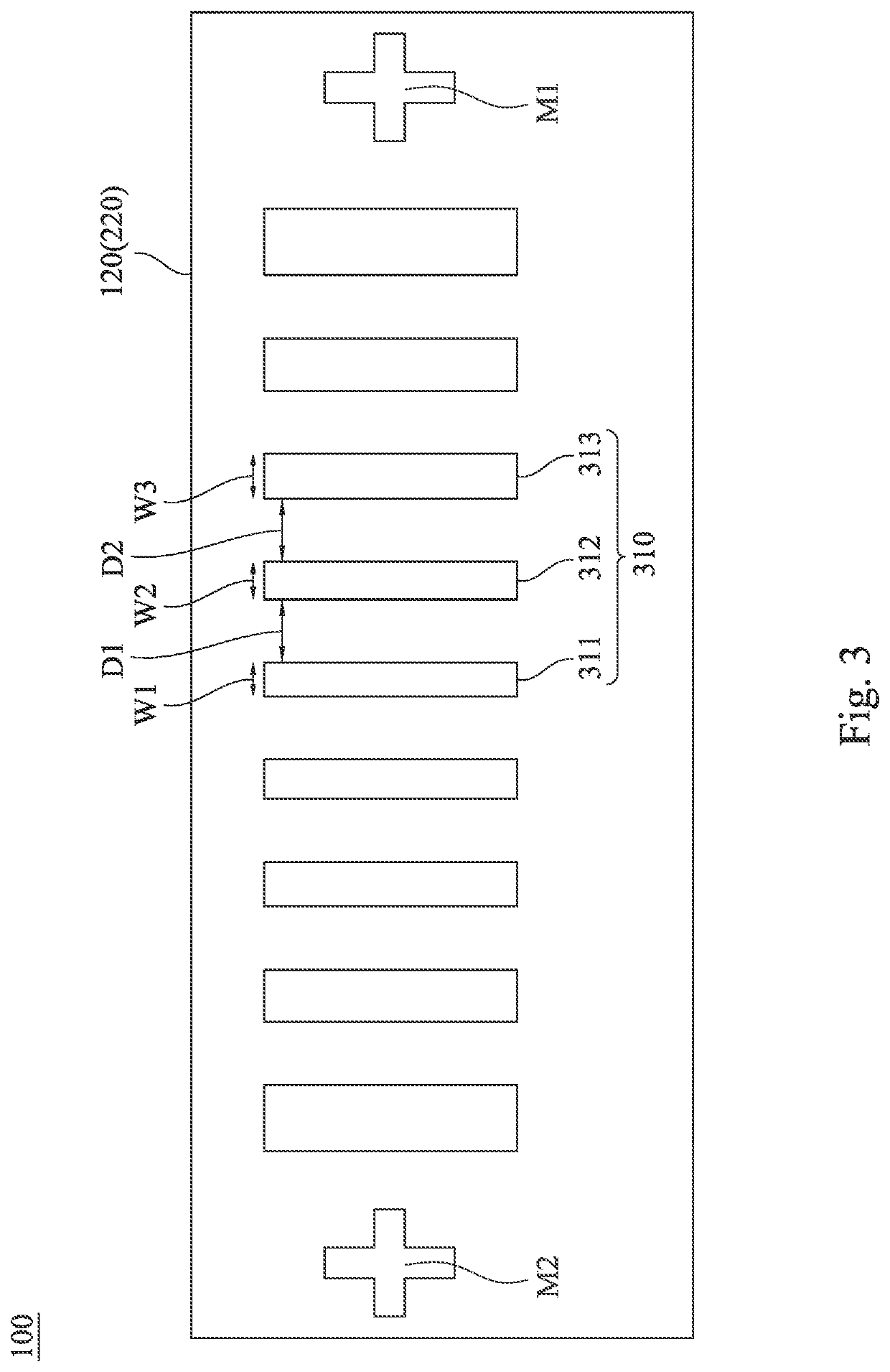

Image

  • Electronic device and method for manufacturing electronic device
  • Electronic device and method for manufacturing electronic device
  • Electronic device and method for manufacturing electronic device

Examples


Embodiment Construction

[0033]Reference will now be made in detail to the present embodiments of the disclosure, examples of which are illustrated in the accompanying drawings. Wherever possible, the same reference numbers are used in the drawings and the description to refer to the same or like parts.

[0034]The terminology used herein is for the purpose of describing particular example embodiments only and is not intended to be limiting of the present disclosure. As used herein, the singular forms “a,”“an” and “the” are intended to include the plural forms as well, unless the context clearly indicates otherwise.

[0035]Furthermore, it should be understood that the terms, “comprising”, “including”, “having”, “containing”, “involving” and the like, used herein are open-ended, that is, including but not limited to.

[0036]The terms used in this specification and claims, unless otherwise stated, generally have their ordinary meanings in the art, within the context of the disclosure, and in the specific context whe...


PUM


Abstract

An electronic device includes a substrate and a flexible printed circuit board. The substrate includes a plurality of first pins disposed on the substrate. The flexible printed circuit board includes a plurality of second pins disposed on the flexible printed circuit board. The first pins and the second pins are bonded to each other to form a plurality of bonding points. The bonding points include at least one central bonding point and at least one first bonding point. The at least one central bonding point is located in a central area of the electronic device. The at least one first bonding point is located in a first area of the electronic device. The first area is located outside the central area. A line width of the at least one first bonding point is greater than a line width of the at least one central bonding point.

Description

BACKGROUNDField of Disclosure[0001]The present disclosure relates to an electronic device and a method. More particularly, the present disclosure relates to an electronic device comprising a touch panel and a method for manufacturing an electronic device.Description of Related Art[0002]The bonding area of the prior art touch panel is designed with equal line width and equal line spacing. The equal line width and equal line spacing are designed according to the maximum common difference of the product, so a sufficient design space is required.[0003]However, with the development of ultra-thin flexible substrate technology, it is impossible to solve the problem of increasing common difference as the length of the bonding area in the product increases.[0004]For the foregoing reason, there is a need to provide some other suitable pin design method to solve the problems of the prior art.SUMMARY[0005]One aspect of the present disclosure provides an electronic device. The electronic device ...

Claims


Application Information

Patent Timeline
Patent Type & Authority Patents(United States)
IPC IPC(8): H05K1/02H05K3/10
CPCH05K1/0296H05K1/028H05K3/10H05K1/118H05K2201/094G06F3/041H05K1/111H05K3/361
Inventor XU, XIAN-BINFU, MING-QIANGLUO, HECHANG, CHEN-HSIN
Owner TPK ADVANCED SOLUTIONS
Learn More