Gas sensor

a gas sensor and sensor technology, applied in the field of gas sensor, can solve the problems of connector electrode corrosion and short circuit between the connector electrodes

Active Publication Date: 2022-07-19
NGK INSULATORS LTD
View PDF38 Cites 1 Cited by
  • Summary
  • Abstract
  • Description
  • Claims
  • Application Information

AI Technical Summary

Benefits of technology

[0016]a water-penetration reduction portion disposed on the side surface so as to divide the porous layer in the longitudinal direction or to be located closer to the rear end than the porous layer, the water-penetration reduction portion being located closer to the front end than the one or more connector electrodes, an overlap length W that is the length of a continuous overlap between a range in which the water-penetration reduction portion is present in the longitudinal direction and a range in which inner peripheral surfaces of the one or more dense bodies are present in the longitudinal direction being 0.5 mm or more, the water-penetration reduction portion including, among a dense layer covering the side surface and having a porosity of less than 10% and a gap region in which the porous layer is absent, the gap region being arranged adjacent to the dense layer, at least the dense layer, the water-penetration reduction portion reducing the capillarity of water in the longitudinal direction.
[0019]In the gas sensor according to the present invention, the length Le of the dense layer in the longitudinal direction may be 20 mm or less. In such a case, for example, in the case where the element main body and the dense layer are prepared by baking an unbaked element main body and an unbaked dense layer, the warpage of the sensor element due to the difference in shrinkage ratio during baking between the unbaked element main body and the unbaked dense layer can be reduced.
[0020]In the gas sensor according to the present invention, the length Le of the dense layer in the longitudinal direction may be 30% or less of the length of the element main body in the longitudinal direction. In such a case, for example, in the case where the element main body and the dense layer are prepared by baking an unbaked element main body and an unbaked dense layer, the warpage of the sensor element due to the difference in shrinkage ratio during baking between the element main body and the dense layer can be reduced.
[0021]In the gas sensor according to the present invention, the length Lg of the gap region in the longitudinal direction may be 1 mm or less. In such a case, since the length Lg of the gap region is relatively small, the area of a part of the side surface of the element main body which is exposed to the outside (the part that is not covered with any of the porous layer and the dense layer) can be reduced.

Problems solved by technology

In such a case, water and the components dissolved in water, such as sulfuric acid, cause rusting and corrosion of the connector electrode and a short circuit between the connector electrodes.

Method used


Image

  • Gas sensor
  • Gas sensor
  • Gas sensor

Examples


experimental example 1

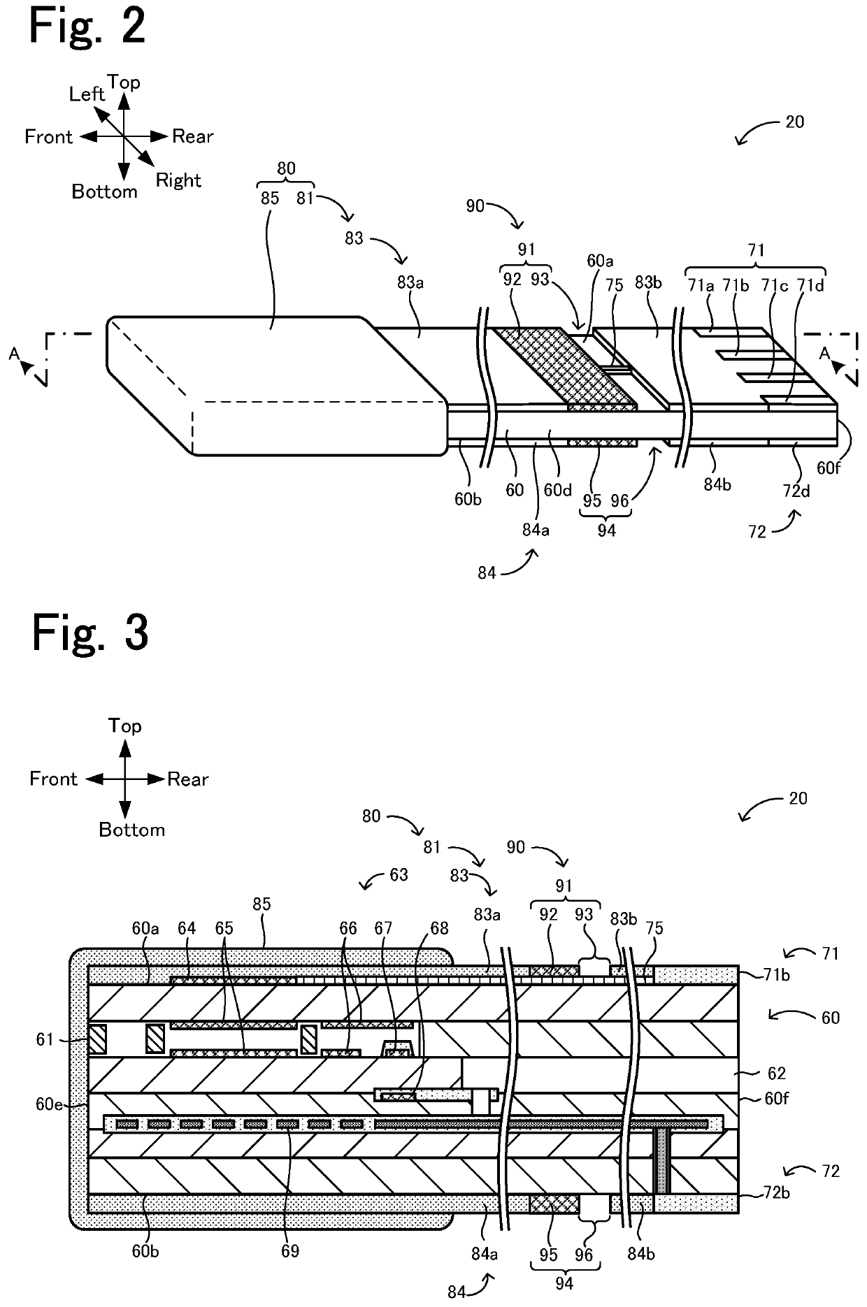
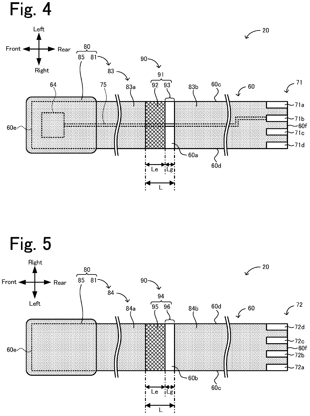
[0093]In Experimental example 1, a sensor element that was the same as the sensor element 20 illustrated in FIGS. 2 to 5, except that the sensor element did not include the first water-penetration reduction portion 91, the second water-penetration reduction portion 94, and the outer porous layer 85, was prepared. That is, in Experimental example 1, the first and second inner porous layers 83 and 84 were arranged to cover the entirety of the first and second surfaces 60a and 60b except the region in which the upper and lower connector electrodes 71 and 72 were disposed. The sensor element 20 of the Experimental example 1 was prepared in the following manner. First, zirconia particles containing 4 mol % yttria serving as a stabilizer were mixed with an organic binder and an organic solvent. The resulting mixture was formed into six ceramic green sheets by tape casting. Patterns of electrodes and the like were printed in each of the green sheets. In addition, unbaked porous layers that...

experimental examples 2 to 31

[0094]In Experimental examples 2 to 31, a sensor element that was the same as that prepared in Experimental example 1, except that the sensor element included the first and second water-penetration reduction portions 91 and 94, was prepared. In Experimental examples 2 to 31, the length Le and the porosity of the first and second dense layers 92 and 95, the length Lg of the first and second gap regions 93 and 96, and the length L of the first and second water-penetration reduction portions 91 and 94 were changed as described in Table 1. The unbaked dense layers that were to be formed into the first and second dense layers 92 and 95 after baking were formed using a slurry that was the same as that used for forming the unbaked porous layers in Experimental example 1, except that the amount of the pore-forming material added to the slurry was reduced. In Experimental examples 2 to 31, the porosity of the first and second dense layers 92 and 95 was changed by adjusting the amount of the ...

experimental example 1a

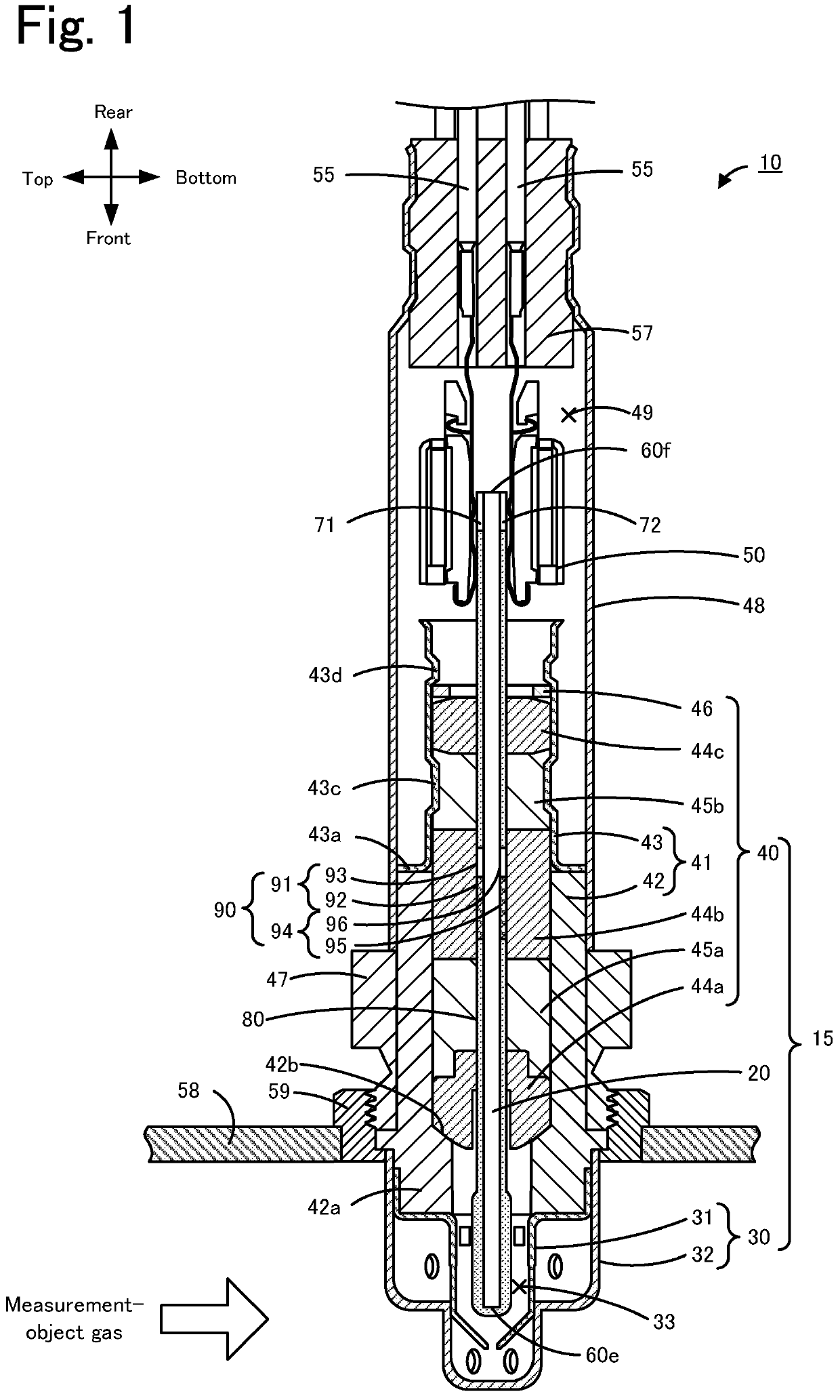
[0103]In Experimental example 1A, a gas sensor 10 having the positional relationship illustrated in FIG. 8 was prepared by the above-described production method. The gas sensor 10 of Experimental example 1A was prepared using a sensor element 20 that was the same as the sensor element 20 prepared in Experimental example 27 except that the positions of the first and second water-penetration reduction portions 91 and 94 in the front-to-rear direction were changed. In the gas sensor 10 of Experimental example 1A, the insulators 44a to 44c were sintered ceramic bodies composed of alumina. The lengths of the insulators 44a, 44b, and 44c in the axial direction were 8 mm, 10 mm, and 4.5 mm, respectively. The porosity of the insulators 44a to 44c determined using a SEM image was less than 1%. The compacts 45a and 45b were formed by molding a talc powder. The amount of the talc powder used was adjusted such that an adequate sealing load was applied to the compacts 45a and 45b inside the cyli...


PUM

PropertyMeasurementUnit
porosityaaaaaaaaaa
lengthaaaaaaaaaa
lengthaaaaaaaaaa

Abstract

A gas sensor includes a sensor element and one or more hollow columnar dense bodies. The sensor element includes an element main body having a side surface, a porous layer and a water-penetration reduction portion that cover at least a front end-side part of the side surface. The water-penetration reduction portion disposed on the side surface so as to divide the porous layer or to be located closer to the rear end than the porous layer, an overlap length W that is the length of a continuous overlap between a range in which the water-penetration reduction portion is present in a longitudinal direction and a range in which inner peripheral surfaces of the one or more dense bodies are present in the longitudinal direction being 0.5 mm or more, and having a dense layer covers the side surface, the water-penetration reduction portion reduces the capillarity of water.

Description

CROSS-REFERENCE TO RELATED APPLICATION[0001]This application is a continuation application of PCT / JP2019 / 001864, filed on Jan. 22, 2019, which claims the benefit of priority of Japanese Patent Application No. 2018-019445, filed on Feb. 6, 2018, the entire contents of which are incorporated herein by reference.BACKGROUND OF THE INVENTION1. Field of the Invention[0002]The present invention relates to a gas sensor.2. Description of the Related Art[0003]Gas sensors that include a sensor element that detects the concentration of a particular gas, such as NOx, in the measurement-object gas, such as an automotive exhaust gas, are known (e.g., PTLs 1 and 2). The sensor element disclosed in PTL 1 includes a multilayer body that includes oxygen ion-conducting solid electrolyte layers stacked on top of one another. This sensor element also includes an outer pump electrode, a lead wire for the outer pump electrode, a connector electrode, and a porous protection layer, which are stacked on and a...

Claims


Application Information

Patent Timeline
Patent Type & Authority Patents(United States)
IPC IPC(8): G01N27/407G01N27/409
CPCG01N27/4077G01N27/409
Inventor NAKAYAMA, YUKIKAGEYAMA, SHOTAFUJII, YUSUKEKOSAKA, KEI
Owner NGK INSULATORS LTD
Why Eureka
Try Eureka