
SCR catalyst device containing vanadium oxide and molecular sieve containing iron

a catalyst device and molecular sieve technology, which is applied in the direction of physical/chemical process catalysts, metal/metal-oxide/metal-hydroxide catalysts, and separation processes, etc., can solve the problems of reducing nitrogen oxides to nitrogen much more difficult, oxidizing ammonia to low-valent nitrogen oxides, and preventing the formation of nitrous oxide. , the effect of preventing the formation of nitrous oxid

Active Publication Date: 2022-04-12
UMICORE AG & CO KG
View PDF38 Cites 0 Cited by
  • Summary
  • Abstract
  • Description
  • Claims
  • Application Information

AI Technical Summary

Benefits of technology

[0030]In particular, catalysts are to be provided that combine the following advantageous properties;
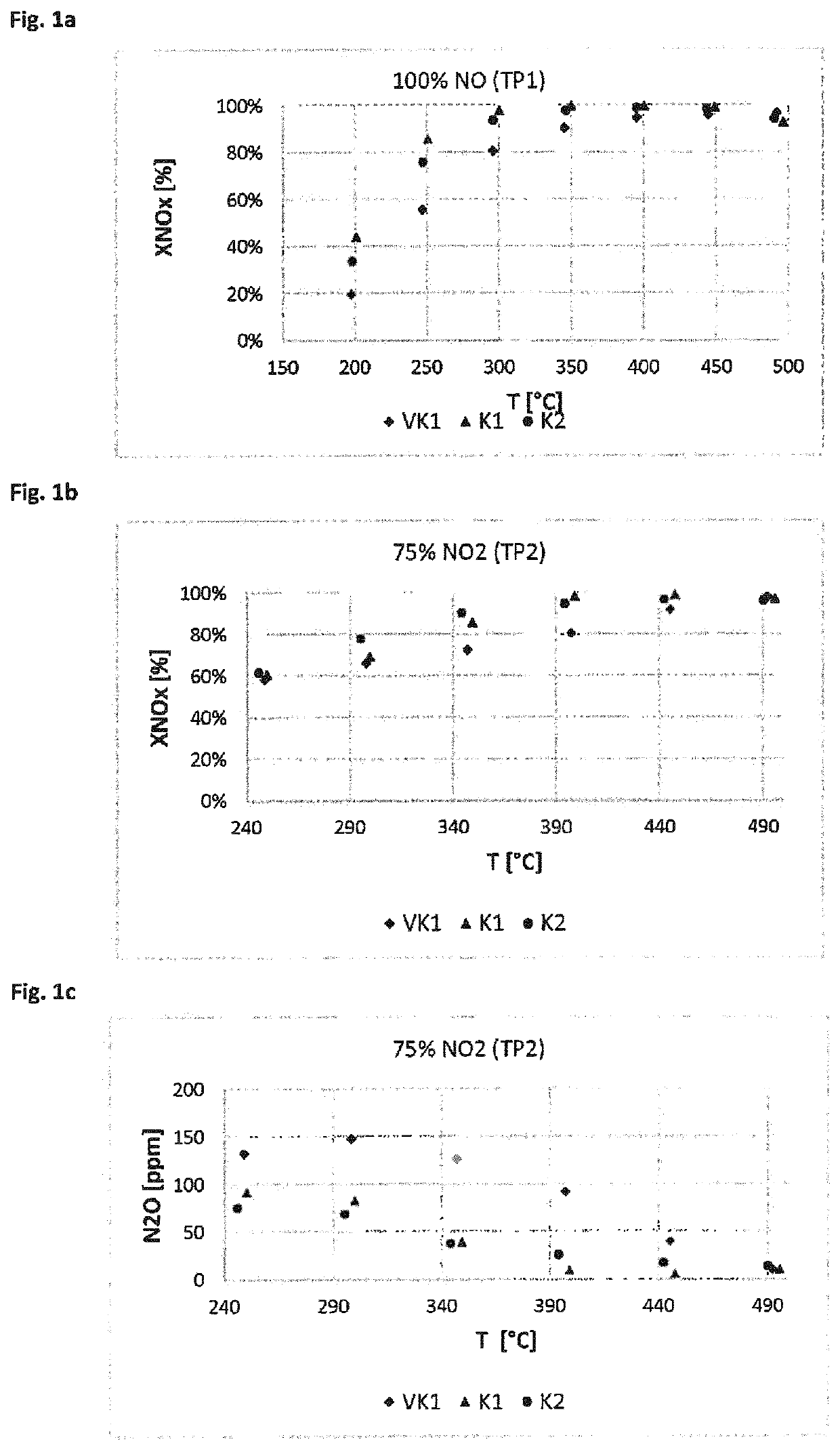
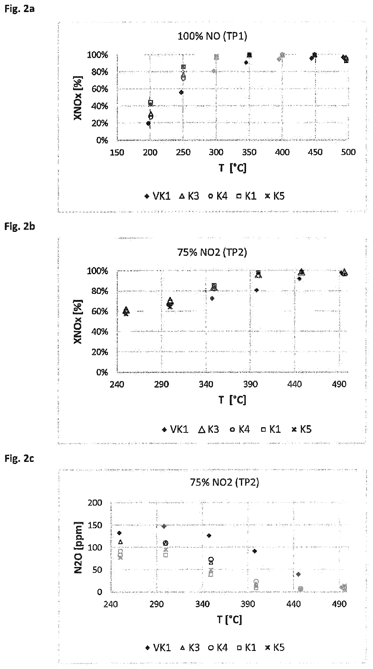
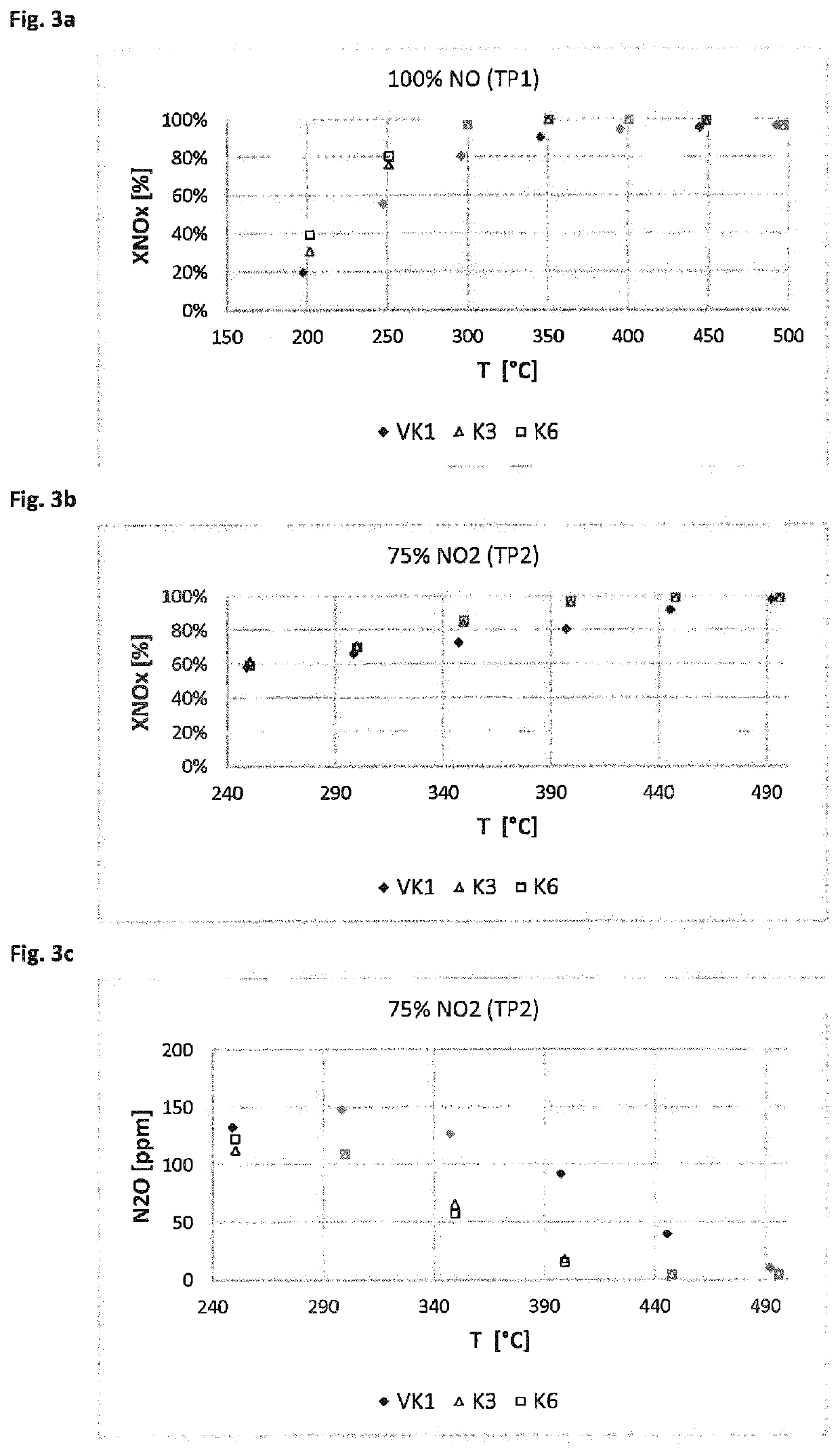
[0114]The catalyst device according to the invention achieves the object underlying the invention. A catalyst device for purifying exhaust gases by SCR is provided, which efficiently removes nitrogen oxides while preventing the formation of nitrous oxide. The device is suitable for purifying exhaust gases over a wide temperature range. It is suitable for purifying exhaust gases rich in NO2 which arise in the operation of diesel engines, for example in conjunction with an oxidation catalyst. Even after aging, the catalyst device exhibits a high level of catalytic activity and prevents or minimizes the formation of nitrous oxide. The effect according to the invention can even be improved by adding cerium oxide to the vanadium catalyst, wherein among other things a further reduction of nitrous oxide, in particular at low temperature, can be achieved. Due to the high efficiency during the SCR under various conditions of use, even at low temperature and with both low and high NO2 contents, the catalyst devices are highly suitable for applications in the automotive field.

Problems solved by technology

The reduction of nitrogen oxides to nitrogen is much more difficult due to the high oxygen content.
In addition, the strongly fluctuating operating conditions cause difficulties with the exact dosing of the ammonia, which should ideally take place in a stoichiometric ratio to the nitrogen oxides to be reduced.
However, the catalyst devices described in the above documents need to be improved, because good nitrogen oxide conversion rates can only be achieved at relatively high temperatures of above approximately 350° C. or above approximately 450° C. As a rule, optimum conversion only takes place within a relatively narrow temperature range.
However, the nitrogen oxides NOx contained in the exhaust gas from lean-burn engines consist predominantly of NO and have only small proportions of NO2.
A further problem with the removal of nitrogen oxides in the exhaust gas of lean-burn engines with SCR catalysts is that the ammonia is oxidized to low-valent nitrogen oxides, especially nitrous oxide (N2O), due to the high oxygen content.
Another problem with conventional catalysts is that nitrous oxide is formed in conventional applications involving combustion engines.
This problem is particularly evident in the middle and low temperature range below about 450° C. or below about 350° C. Exhaust gases from combustion engines often have such temperatures during normal operation, which can lead to the undesirable formation and release of nitrous oxide.
However, the measurements carried out involved SCR catalysts which contained only 0.1 wt % vanadium and are therefore irrelevant in practice.
Thus, the results of the conversion of NO cannot be used to predict results in the conversion of NO2 or of NOx with a high NO2 proportion.

Method used


Image

  • SCR catalyst device containing vanadium oxide and molecular sieve containing iron
  • SCR catalyst device containing vanadium oxide and molecular sieve containing iron
  • SCR catalyst device containing vanadium oxide and molecular sieve containing iron

Examples


example 1

on of the Coating Suspensions (Wash Coats)

[0127]Preparation of Coating Suspension A (Vanadium SCR)

[0128]A commercially available titanium dioxide in the anatase form doped with 5 wt % silicon dioxide was dispersed in water. Next, an aqueous solution of ammonium metatungstate and ammonium metavanadate dissolved in oxalic acid were added as a tungsten or vanadium precursor in an amount such that a catalyst of composition 87.4 wt % TiO2, 4.6 wt % SiO2, 5.0 wt % WO3 and 3.0 wt % V2O5 was the result. The mixture was stirred thoroughly and finally homogenized in a commercially available agitator ball mill and ground to d90<2 μm.

[0129]Preparation of Coating Suspension B (Vanadium SCR with 1% Cerium Oxide)

[0130]A commercially available titanium dioxide in the anatase form doped with 5 wt % silicon dioxide was dispersed in water. Next, an aqueous solution of ammonium metatungstate as a tungsten precursor, ammonium metavanadate dissolved in oxalic acid as a vanadium precursor, and an aqueous ...

example 2

on of the Catalyst Devices

[0135]Various catalyst devices were prepared by coating ceramic substrates with coating suspensions A to D. Conventional ceramic monoliths with parallel flow channels (flow-through substrates) open at both ends were used as substrates. In this case, a first and a second layer (S1, S2) were applied to each substrate, wherein each layer was subdivided into two adjacent zones (Z1, Z2). The exhaust gases to be purified flow in the flow direction into the catalyst device, i.e. via the upper layer 2 and from zone 1 to zone 2. In Scheme 1, the structure of the catalyst devices is shown with four catalytic regions located in two layers and two zones.

[0136]Scheme 1: Schematic Structure of the Catalyst Devices Produced According to the Exemplary Embodiments

[0137]Flow Direction→

[0138]

SubstrateLayer 2 Zone 1Layer 2 Zone 2(S2Z1)(S2Z2)Layer 1 Zone 1Layer 1 Zone 2(S1Z1)(S1Z2)

[0139]The compositions and the amounts of coating suspensions A to D used are summarized in Table ...

example 3

of Nitrogen Oxides by SCR

[0146]Measurement Method

[0147]The catalyst devices prepared according to Example 2 were tested for their activity and selectivity in the selective catalytic reduction of nitrogen oxides. In doing so, the nitrogen oxide conversion was measured at various defined temperatures (measured on the inlet side of the catalyst) as a measure of the SCR activity and the formation of nitrous oxide. On the inlet side, model exhaust gases containing preset proportions of NO, NH3, NO2 and O2, among other things, were introduced. The nitrogen oxide conversions were measured in a reactor made of quartz glass. Drill cores with L=3″ and D=1″ were tested between 190 and 550° C. under steady-state conditions. The measurements were taken under the test conditions summarized below. GHSV is the gas hourly space velocity (gas flow rate:catalyst volume). The conditions of measurement series TP1 and TP2 are summarized below:

[0148]Test Parameter Set TP1:

[0149]Gas hourly space velocity G...


PUM

PropertyMeasurementUnit
temperatureaaaaaaaaaa
kinetic pore diameteraaaaaaaaaa

Abstract

The invention relates to a catalyst device for purifying exhaust gases containing nitrogen oxide by using selective catalytic reduction (SCR), the catalyst device comprising at least two catalytic layers, the first layer containing vanadium oxide and a mixed oxide comprising titanium oxide and silicon oxide and the second layer containing a molecular sieve containing iron, wherein the first layer is applied onto the second layer. The invention also relates to uses of the catalyst device and a method for purifying exhaust gases.

Description

[0001]The invention relates to a catalyst device for purifying exhaust gases containing nitrogen oxide by using selective catalytic reduction (SCR), comprising at least two catalytic layers, the first layer containing vanadium oxide and the second layer containing a molecular sieve containing iron, wherein the first layer is applied onto the second layer. The invention also relates to uses of the catalyst device and to methods for purifying exhaust gases.PRIOR ART[0002]The method of selective catalytic reduction (SCR) is used in the prior art for reducing nitrogen oxides in exhaust gases, for example, from combustion plants, gas turbines, industrial plants or combustion engines. The chemical reaction is carried out with selective catalysts, hereinafter referred to as ‘SCR catalysts,’ which selectively remove nitrogen oxides, especially NO and NO2, by reduction. In contrast, undesirable side reactions are suppressed. In the reaction, a reductant containing nitrogen is fed in, usually...

Claims


Application Information

Patent Timeline
Patent Type & Authority Patents(United States)
IPC IPC(8): F01N3/28F01N3/20B01J21/06B01J23/22
CPCF01N3/2803B01J21/063F01N3/2073B01J23/22F01N2370/04F01N2510/0684F01N2610/02B01D53/9418B01J29/7615F01N3/2066B01D2251/2062B01D2251/2067B01D2255/20723B01D2255/20738B01D2255/50B01D2255/9022B01D2257/404Y02C20/10B01J23/002B01J29/76B01J2523/55B01J2523/69B01J2523/3712B01J2523/47B01J2523/41B01J2523/31
Inventor MALMBERG, STEPHANSOEGER, NICOLA
Owner UMICORE AG & CO KG
Learn More