
Magnetic rod guide for a filter

a technology of magnetic rods and filters, applied in the field of magnetic rod guides for filters, can solve the problems of heavy weight of the lid carrying magnets, significant force added to the removal of the lid, and difficult or even impossible to remove the lid without mechanical assistan

Active Publication Date: 2022-03-01
ADEY HLDG
View PDF21 Cites 0 Cited by
  • Summary
  • Abstract
  • Description
  • Claims
  • Application Information

AI Technical Summary

Benefits of technology

Facilitates easier servicing and maintenance by reducing the force needed to remove the lid and minimizing magnet corrosion, allowing for effective cleaning without disassembly and extending the filter's operational life.

Problems solved by technology

A problem in carrying out this servicing is that the lid carrying the magnets is fairly heavy.
Also, the filter pot is generally magnetic and this can add significantly to the force required to remove the lid.
If the filter is not at, for example, ground level, but is at chest height or above, it can be extremely difficult, or even impossible to remove the lid without some sort of mechanical assistance.
This can add significantly to the costs of servicing.
Another problem is that if the seals around the top of the magnets break down, then heating system water can rust the magnets themselves, making them less effective or substantially ineffective over time.

Method used


Image

  • Magnetic rod guide for a filter
  • Magnetic rod guide for a filter
  • Magnetic rod guide for a filter

Examples


Embodiment Construction

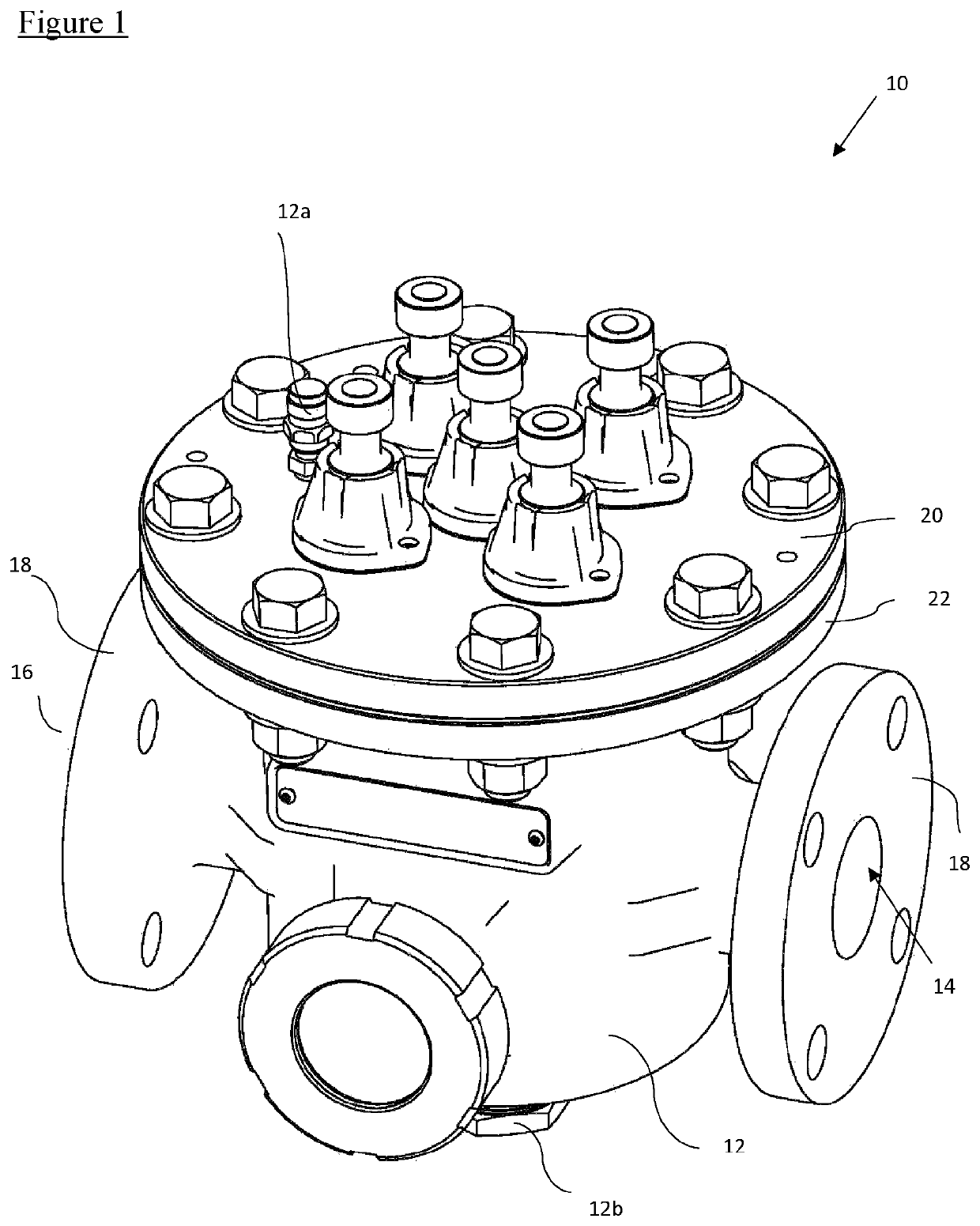
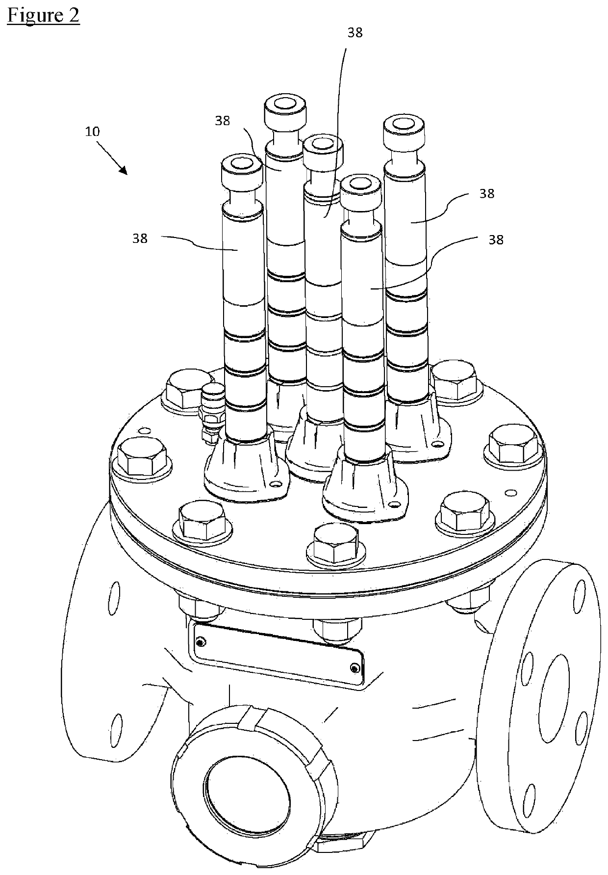
[0037]Referring firstly to FIG. 1, a magnetic filter is indicated generally at 10. The filter 10 has a body 12, typically manufactured as a cast pot. The body 12 includes a chamber. An inlet 14 and an outlet 16 are provided on either side of the body 12, but flow direction is unimportant and the filter can be positioned in a flow pipe in either orientation. In use, valves, not shown, are position on either side of the filter so that it can be isolated from a heating circuit. The inlet and outlet 14, 16 are each formed by circular flange 18 bounding a circular aperture in communication with the inside of the body 12. The filter is intended to be used in a hot water heating system and has an operating pressure of up to 10 bar. The filter 10 includes a bleed valve 12a and a drain 12b.

[0038]A lid 20 of the filter 10 is provided in the form of a circular plate, which is bolted to a circular flange 22 provided at the top of the filter 10. A rubber seal (not shown) sits between the lid 20...


PUM

PropertyMeasurementUnit
diameteraaaaaaaaaa
diameteraaaaaaaaaa
pressureaaaaaaaaaa

Abstract

A magnetic rod guide for a filter is provided that includes a base for attachment to part of a filter, a through aperture through which a magnetic rod can move, and resilient engagement means. The resilient engagement means includes one or more resilient latches for holding the magnetic rod in one or more fixed positions relative to the guide. Each resilient latch is adapted to allow movement of the magnetic rod through the through aperture in either direction, for insertion into the filter or withdrawal from the filter into one of the fixed positions.

Description

CROSS-REFERENCE TO RELATED APPLICATIONS[0001]This patent application is a United States National Stage Patent Application of International Patent Application No. PCT / GB2017 / 051947, filed Jun. 30, 2017, which in turn claims the benefit of Great Britain Patent Application No. 1611514.9, filed Jun. 30, 2016. The entire disclosures of the above patent applications are hereby incorporated herein by reference.FIELDBackground to the Invention[0002]Magnetic filters are used to collect ferrous particles in suspension in piped water systems, for example, in heating systems. Large heating systems, for example, which use 2 inch (around 50 mm) or greater diameter pipe for the heating circuit(s) generally require a reasonably large filter. Filters sold under the trade mark MAGNACLEAN™ COMMERICAL, for example, fit into this category.[0003]These filters generally take the form of a large, heavy, cast or fabricated container, with an inlet and an outlet on either side, a removable lid, and magnets e...

Claims


Application Information

Patent Timeline
Patent Type & Authority Patents(United States)
IPC IPC(8): B01D35/06B03C1/28
CPCB01D35/06B03C1/286B01D2201/305B03C1/284B03C2201/18B03C2201/28B03C1/0332B03C1/288C02F1/488F24D19/0092H01F7/0221C02F1/48
Inventor DOWNIE, SIMONPATHAN, KASHEMALBROW, ROBERT
Owner ADEY HLDG
Learn More