Reducing controller updates in a control loop

a controller and update technology, applied in the field of implementing control in a control loop, can solve the problems of reducing the efficiency and/or profitability of the process control system, controllers, and compromising the integrity of communications between one or more field devices, and achieve the effect of improving the control performance of pid controllers

Active Publication Date: 2021-12-14
FISHER-ROSEMOUNT SYST INC
View PDF163 Cites 0 Cited by
  • Summary
  • Abstract
  • Description
  • Claims
  • Application Information

AI Technical Summary

Benefits of technology

[0017]A control technique that may be used in, for example, a PID control loop, significantly reduces the number of communications from the controller (e.g., a PID controller) to a wireless valve or other control element within a process plant, while still providing robust control of a controlled process variable. As such, the wireless valve or other control element may use less power because the valve must react to fewer changes in the target valve position, while still providing acceptable and robust control. Moreover, using this control technique in a plant in which the controller is communicatively connected to a controlled device via a gateway into a wireless network will reduce gateway communications loading, as this technique can result in fewer communications to the wireless valve or other controlled element. This control technique may be used in conjunction with other intermittent or non-periodic control methods, and so may perform control using one or both of a wireless transmitter and a wireless valve (or other wireless control element) in a control loop. Moreover, this technique can be used to perform control in a wired or other periodic control system to reduce unnecessary or ineffective valve movements, such as valve position hunting which is typically experienced in noisy control systems, such as those in which feedback measurements include noise or in which noise results in relatively random process disturbances.
[0018]In addition, a new control signal command may be used to send control signals via a wireless or other intermittent, non-periodic or asynchronous communications network so as to aid in the control performance of the control technique described herein. The new controller signal may include both a target value and a time to implement the target value. This command signal or other signal allows an implied valve position to be calculated more accurately at the controller, and thus may be used to perform better or more robust control in a system that experiences significant communication delays in the process control loop communications (e.g., between a process controller and a controlled device such as a valve).
[0019]Generally speaking, a control loop implementing the new non-periodic communication technique may include a wireless, slow, non-periodic, or non-synchronized communication connection or path between a controller implementing a control routine (such as a PID control routine) and a controlled device, such as a valve or a valve actuator. The link could be implemented using a wireless or a wired communication infrastructure. In this case, the control technique uses a non-periodic communication block disposed between the controller and the controlled device, wherein the communication block operates to minimize the number of changes made in the target position of the controlled device by reducing the number of control signals that are sent to the controlled device.
[0020]More particularly, to minimize the power consumed by the valve actuator, the calculated PID output of the controller may be transmitted to the wireless valve only if specific criteria determined by the non-periodic communication block have been met. As the controller is typically scheduled to execute to produce a control signal much faster than the minimum period at which the target value can be communicated to the wireless controlled device, the application of these criteria will reduce the number of controller signals sent to the controlled device and thereby reduce controller moves implemented by the controlled device. However, the application of the criteria within the communication block still operates to assure that adequate control performance is achieved in the presence of the reduced number of control signals and the communication delays of the control signals to a controlled device. As an example, the non-periodic communication block may operate to communicate a new target position to the controlled device (via the wireless, intermittent, non-synchronized or non-periodic communication path) in the following manner. First, the non-periodic communication block will only send a control signal if the time since the last communication to the wireless controlled device is equal to or greater than the configured period of communication, and a communication of a controlled device acknowledgement to the last change in target position sent to the controlled device has been received. When these conditions are met, then the non-periodic communication block will communicate a new or updated control signal when either or both the absolute value of the difference between the calculated controller output and the last target value communicated to the controlled device exceeds a configured deadband (threshold) value and / or when the time since the last communication to the controlled device exceeds a configured default reporting time.
[0022]When minimal delay is introduced by communications between a wireless controlled device and a controller, then a feedback signal in the form of a position of a valve, as communicated by the wireless controlled device (e.g., an actuator / valve) to the controller, may be used in the controller positive feedback network to create, for example, a reset contribution of a PID control signal. However, if communications with the wireless controlled device are lost or are not updated in a periodic manner, then the feedback of the last target position of the controlled device (e.g., the target position that a valve actuator is working to achieve) communicated by the wireless valve may be used to determine the reset contribution of the controller operation. To assist the feedback loop of the control system in determining the valve position for use in calculating the reset contribution, the control system (or wireless gateway) may provide a control signal that specifies a control value (e.g., a position to which a valve should move) and a time at which the valve should make such a movement. Such a control signal is useful in situations in which the time it takes for the control signal to reach the controlled device is significant (e.g., caused by a wireless gateway or other slow or non-synchronized communication link). The time specified within the control signal may specify an absolute time or an offset time from, for example, the timestamp of the control signal. If the offset time is configured to be greater than the time that it takes the control signal to reach the controlled device from the controller, then the controlled device will receive the control signal and implement the change at the specified time. In this case, the controller can assume that the control signal was received and implemented by the controlled device at the specified time and so can update the valve position in the feedback loop of the controller at that time, without needing to receive a feedback signal from the controlled device indicting that the controller move was implemented. This operation may result in better control performance in a PID controller.

Problems solved by technology

These factors and conditions can compromise the integrity of communications between one or more field devices, controllers, etc.
Compromised control communications could therefore result in reduced process control system efficiency and / or profitability, and excessive wear or damage to equipment, as well as any number of potentially harmful failures.
Unfortunately, hardwired networks introduce a number of complexities, challenges and limitations.
For example, the quality of hardwired networks may degrade over time.
Moreover, hardwired I / O communication networks are typically expensive to install, particularly in cases where the I / O communication network is associated with a large industrial plant or facility distributed over a large area, for example, an oil refinery or chemical plant consuming several acres of land.
The requisite long wiring runs typically involve substantial amounts of labor, material and expense, and may introduce signal degradation arising from wiring impedances and electromagnetic interference.
For these and other reasons, hardwired I / O communication networks are generally difficult to reconfigure, modify or update.
However, reliance on wireless communications for control-related transmissions has traditionally been limited due to, among other things, reliability concerns.
Undesirable environmental factors or other adverse conditions may create intermittent interferences that impede or prevent the fast or periodic communications necessary to support such execution of monitoring and control algorithms.
However, power consumption is still a complicating factor when using wireless communications in process control applications.
For these devices, energy consumed for data transmission may constitute a significant portion of total energy consumption.
In fact, more power may be consumed during the process of establishing and maintaining a wireless communication connection than during other important operations performed by the field device, such as the steps taken to sense or detect the process variable being measured.
In one case, the field devices may communicate with or send process variable measurements to the controller only when a significant change in a process variable has been detected, leading to non-periodic communications with the controller.
However, there are a couple of technical challenges that must be addressed to be able to use such wireless valves in closed loop control.
In particular, there is typically only a limited amount of power available at the wireless valve, and it is anticipated that much of the available power will be required to make changes in the target valve position, e.g. to drive the valve to its target position in response to the receipt of a control signal.
However, the high number of controller based moves implemented by these techniques may quickly use up the battery resources at the controlled device.
Moreover, in many cases, the control system actions cannot be synchronized with gateway communications that must occur to provide communications between a controller and a wireless valve or other actuator disposed in a wireless communication network.
Thus, in this case, the wireless communication of the target valve position (e.g., the control signal) and the valve response introduces a significant variable delay into the control loop, and this delay that impacts PID control, making robust control of the controlled variable more difficult.
Moreover, using this control technique in a plant in which the controller is communicatively connected to a controlled device via a gateway into a wireless network will reduce gateway communications loading, as this technique can result in fewer communications to the wireless valve or other controlled element.

Method used


Image

  • Reducing controller updates in a control loop
  • Reducing controller updates in a control loop
  • Reducing controller updates in a control loop

Examples


Embodiment Construction

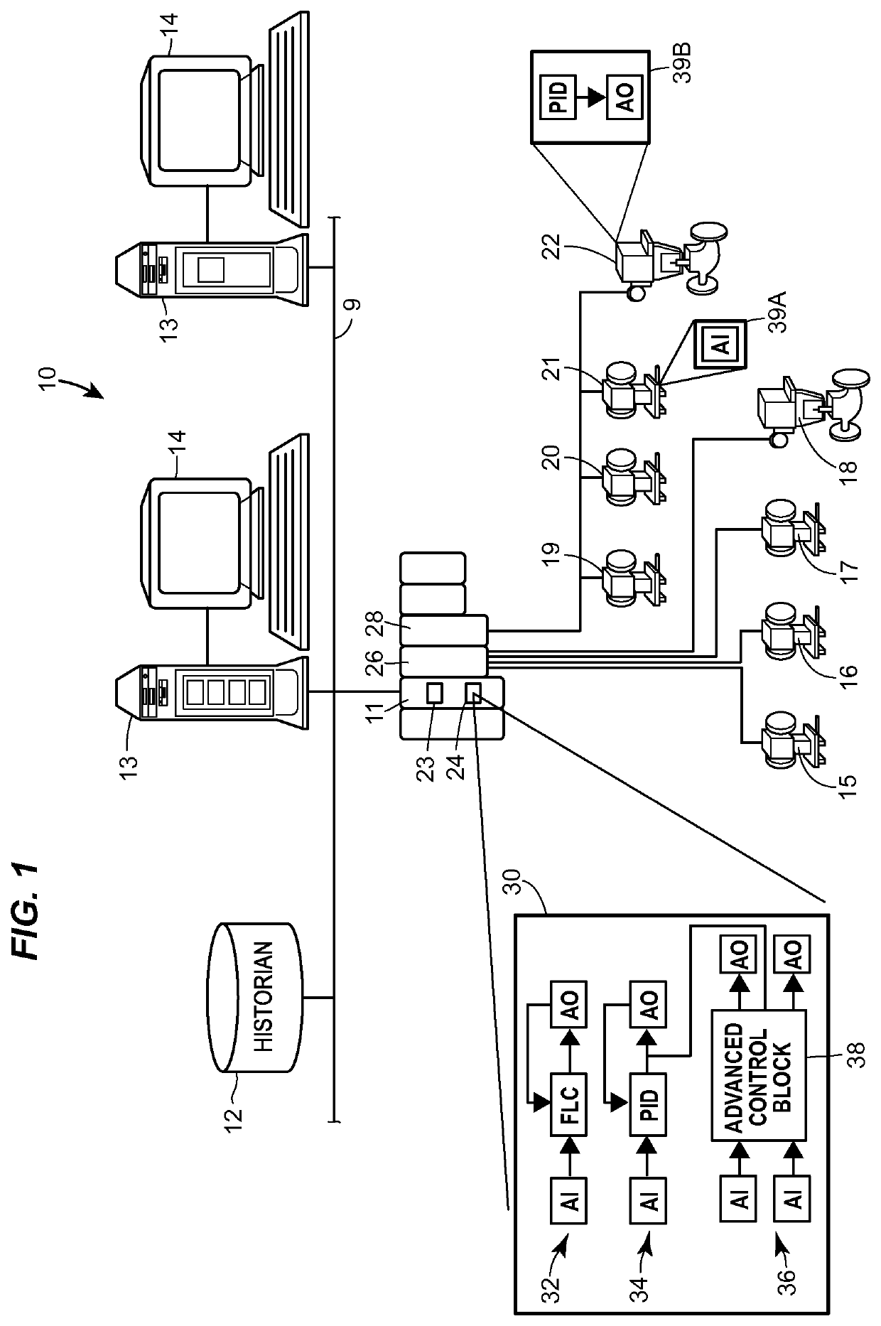
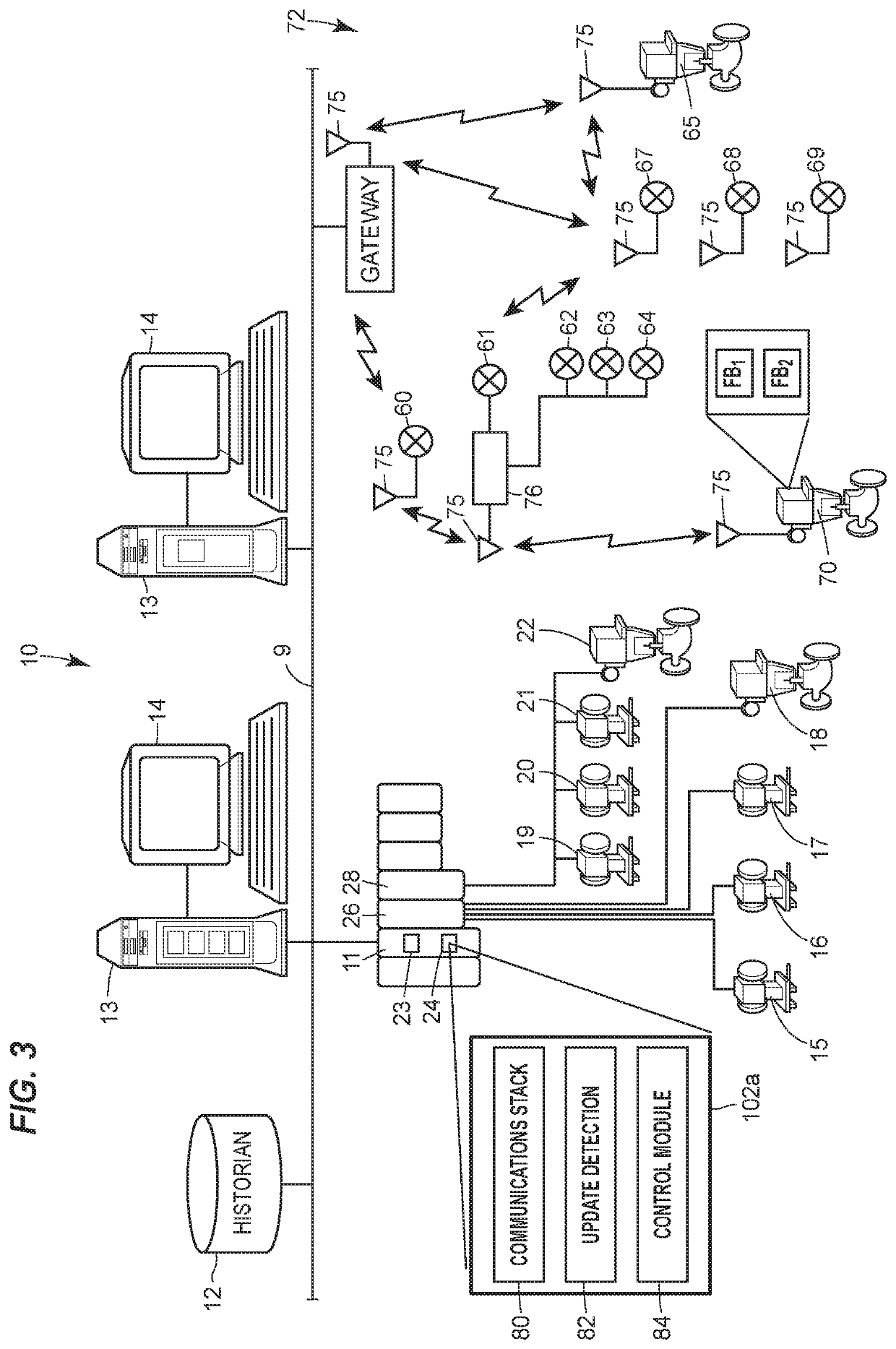
[0032]A control technique enables a controller to communicate or send control signals to a controlled device of a process, such as a valve actuator, in a non-periodic, wireless, slow, significantly delayed or otherwise non-synchronous manner, to reduce the number of actuator moves effectuated by the actuator while still providing robust control performance. As such, the control technique implements a control methodology that drives an actuator or other controlled device in a manner that reduces the power consumption of the controlled device, reduces frequent changes of the controlled device that result in a “hunting” phenomena that frequently occurs in control loops that experience significant noise or process disturbances, and reduces communication loading in communication devices within a wireless network that is used to implement a control loop, such as in wireless gateway devices.

[0033]In particular, a control communications block within a control loop operates to send newly cre...


PUM


Abstract

A control technique controls a process in a manner that reduces the number of controller changes provided to a controlled device, and so reduces the power consumption of the controlled device along with the loading of a process control communications network disposed between the controller and the controlled device. This technique is very useful in a control system having wirelessly connected field devices, such as sensors and valves which, in many cases, operate off of battery power. Moreover, the control technique is useful in implementing a control system in which control signals are subject to intermittent, non-synchronized or significantly delayed communications and / or in a control system that receives intermittent, non-synchronized or significantly delayed process variable measurements to be used as feedback signals in the performance of closed-loop control.

Description

RELATED APPLICATIONS[0001]This application is a regular-filed application claiming priority to U.S. Provisional Patent Application Ser. No. 61 / 968,159 entitled “Reducing Controller Updates in a Control Loop,” filed Mar. 20, 2014, the entire disclosure of which is hereby expressly incorporated herein by reference. This application is also a continuation-in-part of U.S. patent application Ser. No. 13 / 351,802 entitled “Compensating for Setpoint Changes in a Non-Periodically Updated Controller,” filed Jan. 17, 2012, the entire disclosure of which is hereby expressly incorporated herein by reference. This application is also related to U.S. patent application Ser. No. 11 / 850,810 entitled “Wireless Communication of Process Measurements,” filed Sep. 6, 2007, which is a continuation-in-part of U.S. patent application Ser. No. 11 / 499,013 entitled “Process Control With Unreliable Communications,” filed Aug. 4, 2006 and issued as U.S. Pat. No. 7,620,460, which is a continuation-in-part of U.S....

Claims


Application Information

Patent Timeline
Patent Type & Authority Patents(United States)
IPC IPC(8): G05B17/02
CPCG05B17/02
Inventor BLEVINS, TERRENCE L.NIXON, MARK J.JENSEN, KURTIS K.PANTHER, MITCHELL S.CHEN, DEJIROTVOLD, ERIC D.
Owner FISHER-ROSEMOUNT SYST INC
Why Eureka
Try Eureka