Turbine housing of a turbocharger

a technology of turbocharger and turbine housing, which is applied in the direction of gas turbine plants, combustion engines, machines/engines, etc., can solve the problems of reducing and the failure of the turbocharger as a whole, so as to reduce the relative displacement between the valve seat and the bushing axis, improve the performance of the wastegate assembly, and reduce the thermal deformation of the wastegate port wall

Active Publication Date: 2021-09-28
BORGWARNER INC
View PDF7 Cites 0 Cited by
  • Summary
  • Abstract
  • Description
  • Claims
  • Application Information

AI Technical Summary

Benefits of technology

[0008]A turbocharger for receiving exhaust gas from an internal combustion engine of a vehicle and for delivering compressed air to the internal combustion engine includes a turbine housing. The turbine housing includes a turbine inlet wall defining an inlet passage configured to be in fluid communication with the internal combustion engine for receiving exhaust gas from the internal combustion engine, an exducer shroud wall defining an exducer interior disposed downstream of and in fluid communication with the inlet passage for receiving exhaust gas from the inlet passage, and a turbine outlet wall defining an outlet passage disposed downstream of and in fluid communication with the exducer interior for receiving exhaust gas from the exducer interior. The turbine housing also includes a wastegate port wall defining a wastegate channel disposed downstream of and in fluid communication with the inlet passage for discharging exhaust gas from the inlet passage to the outlet passage by bypassing the exducer interior. The wastegate port wall defines a wastegate channel outlet disposed downstream of the wastegate channel for discharging exhaust gas into the outlet passage. The turbine housing further includes a bushing wall coupled to the wastegate port wall and defining a bushing boss extending along a bushing axis. The bushing wall is spaced from the turbine inlet wall such that the wastegate port wall is disposed between the bushing wall and the turbine inlet wall. The turbine housing also includes a valve seat disposed about the wastegate channel at the wastegate channel outlet of the wastegate channel. The turbocharger also includes a wastegate assembly for controlling exhaust gas flow through the wastegate channel. The wastegate assembly includes a valve element engageable with the valve seat. The valve element is moveable between a first position for preventing exhaust gas flow from the inlet passage to the outlet passage by bypassing the exducer interior, and a second position for allowing exhaust gas flow from the inlet passage to the outlet passage by bypassing the exducer interior. The wastegate port wall is disposed outside of the exducer interior such that the wastegate port wall and the bushing wall are configured to be thermally decoupled from the turbine inlet wall and such that relative displacement between the valve seat and the bushing axis is reduced during operation of the turbocharger.
[0009]Accordingly, the wastegate port wall being disposed outside of the exducer interior such that the wastegate port wall and the bushing wall are configured to be thermally decoupled from the turbine inlet wall and such that relative displacement between the valve seat and the bushing axis is reduced during operation of the turbocharger improves performance of the wastegate assembly and the turbocharger. Having the wastegate port wall disposed outside of the exducer interior allows the wastegate port wall to be exposed to an outer environment, which results in cooling of the wastegate port wall and reducing thermal deformation of the wastegate port wall. Reducing thermal deformation of the bushing wall and the wastegate port wall increases performance of the wastegate assembly and of the turbocharger as a whole. Specifically, as the thermal deformation of the bushing wall and the wastegate port wall is reduced, the valve element is able to improve sealing of the wastegate channel by engaging the valve seat, which results in increased performance of the turbocharger and the ability of the turbocharger to operate over an entire operating range of the internal combustion engine. In particular, the valve element is able to accurately move to the first position to seal the wastegate channel, the rotational speed of a turbine wheel in the exducer interior is able to reach rotational targets, and the internal combustion engine is able to meet performance targets due to performance of the turbocharger.

Problems solved by technology

In typical turbine housings, thermal deformation of the turbine housing can cause relative movement between various features of the turbocharger, which can result in decreased performance and, at times, failure of the turbocharger.
For example, movement of the valve element with respect to the valve seat due to different rates of thermal deformation of the turbine housing can lead to decreased performance in the wastegate assembly and of the turbocharger as a whole.
Specifically, as the bushing wall and the wastegate port wall thermally deform with respect to each other at different rates, the valve element is no longer able to properly engage the valve seat to seal the wastegate channel, which results in decreased performance of the turbocharger and an inability of the turbocharger to operate over an entire operating range of the internal combustion engine.
In particular, the valve element is unable to accurately move to the first position to seal the wastegate channel by engaging the valve seat, the rotational speed of a turbine wheel in the exducer interior is unable to reach rotational targets as a result of poor sealing of the wastegate channel, and the internal combustion engine will not meet performance targets due to poor performance of the turbocharger as a whole.
These problems are caused, in part, due to wastegate port wall being disposed in the exducer shroud wall in conventional turbine housings.
Having the wastegate port wall subjected to the hottest stream of exhaust gas results in the wastegate port having greater thermal deformation than the bushing wall, which results in relative movement between the valve element and the valve seat and leads to poor sealing of the wastegate channel.

Method used


Image

  • Turbine housing of a turbocharger
  • Turbine housing of a turbocharger
  • Turbine housing of a turbocharger

Examples


Embodiment Construction

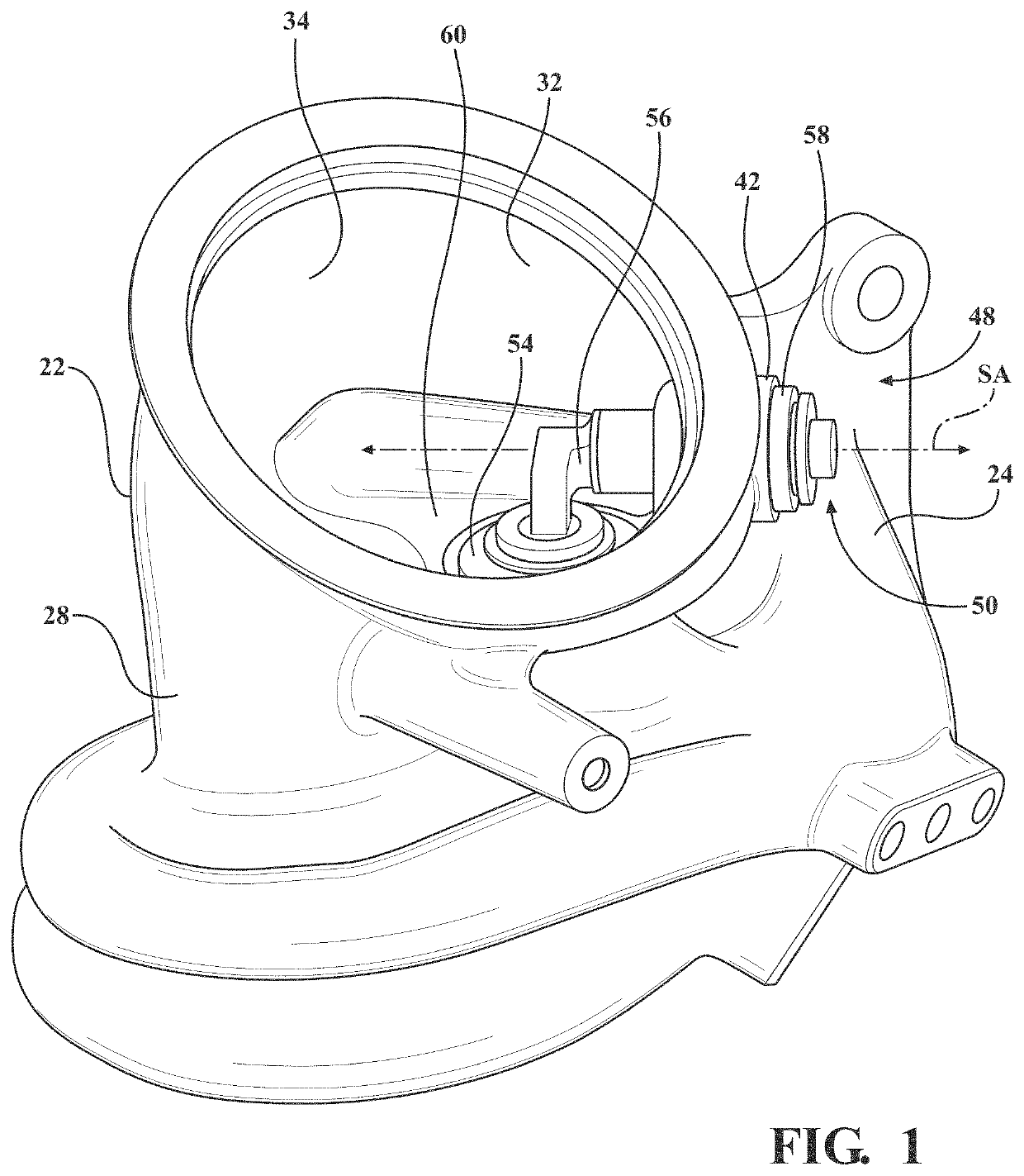
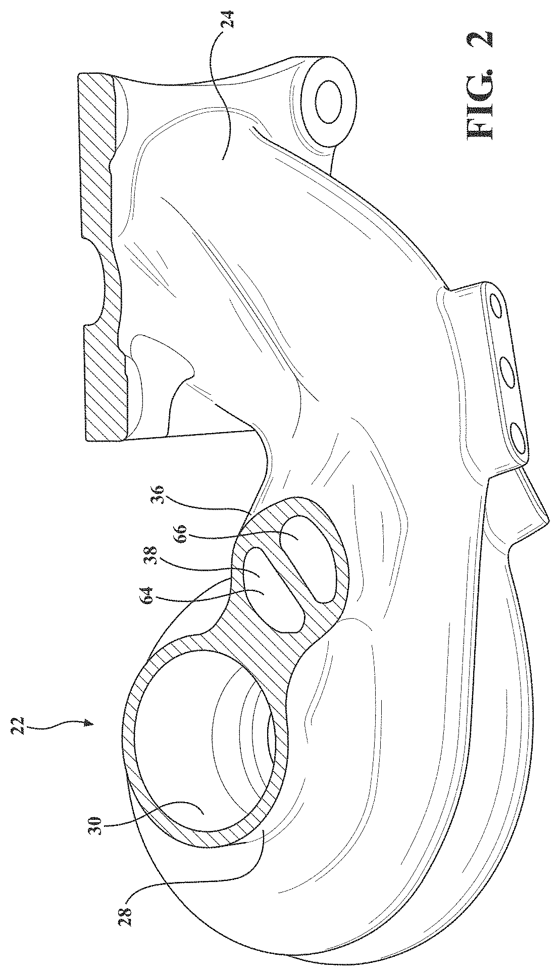
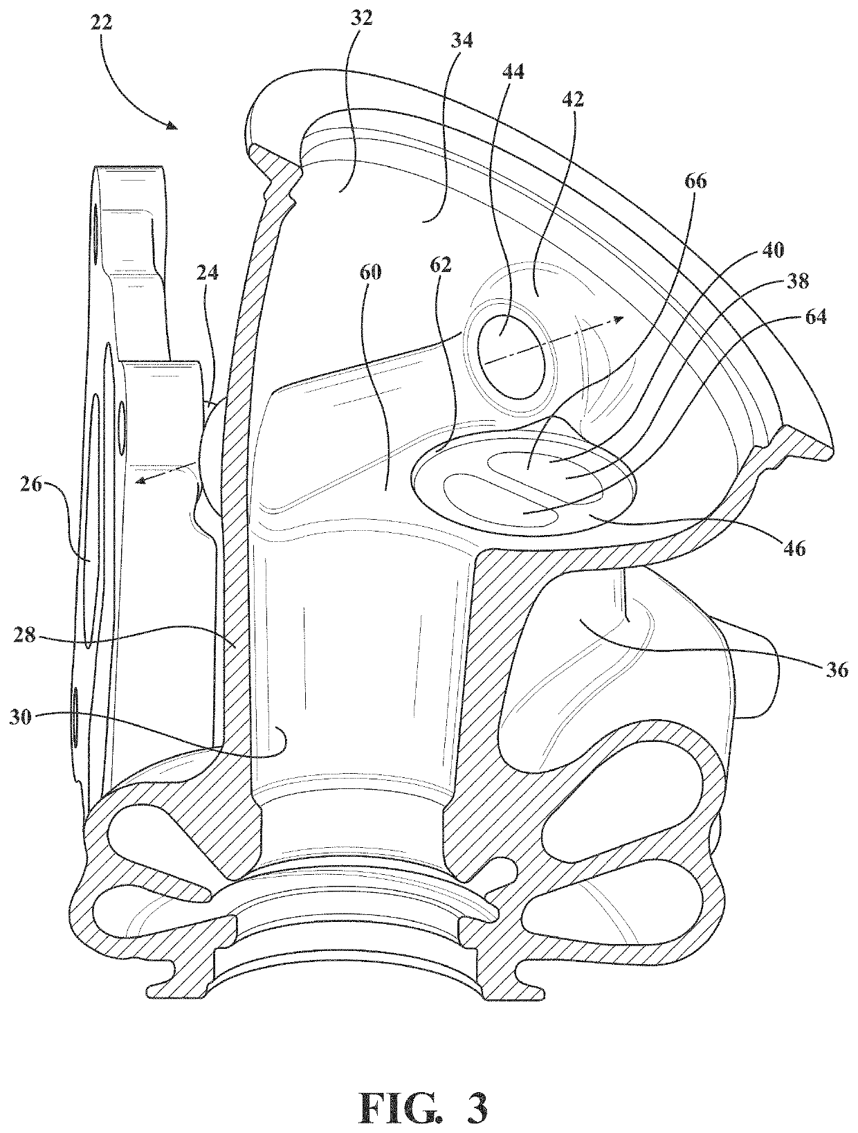
[0017]With reference to the Figures, wherein like numerals indicate like parts throughout the several views, a turbocharger 20, which is schematically shown in FIG. 6, for receiving exhaust gas from an internal combustion engine of a vehicle and for delivering compressed air to the internal combustion engine includes a turbine housing 22, which is shown in FIGS. 1-5. With particular reference to FIG. 3, turbine housing 22 includes a turbine inlet wall 24 defining an inlet passage 26 configured to be in fluid communication with the internal combustion engine for receiving exhaust gas from the internal combustion engine. The inlet passage 26 may be a single volute inlet passage, or may be a multiple volute passage, such as a twin-scroll configuration, as shown in FIG. 5. With reference to FIGS. 1-4, the turbine housing 22 also includes an exducer shroud wall 28 defining an exducer interior 30 disposed downstream of and in fluid communication with the inlet passage 26 for receiving exh...


PUM


Abstract

A turbocharger includes a turbine housing. The turbine housing includes a turbine inlet wall defining an inlet passage, an exducer shroud wall defining an exducer interior, a turbine outlet wall defining an outlet passage, a wastegate port wall defining a wastegate channel, and a bushing wall coupled to the wastegate port wall and defining a bushing boss extending along a bushing axis, and a valve seat disposed about the wastegate channel. The turbocharger also includes a wastegate assembly. The wastegate assembly includes a valve element engageable with the valve seat. The wastegate port wall is disposed outside of the exducer interior such that the wastegate port wall and the bushing wall are configured to be thermally decoupled from the turbine inlet wall and such that relative displacement between the valve seat and the bushing axis is reduced during operation of the turbocharger.

Description

BACKGROUND OF THE INVENTION1. Field of the Invention[0001]The present invention generally relates to a turbine housing and, more specifically, to a turbocharger including a wastegate assembly and the turbine housing.2. Description of the Related Art[0002]Turbochargers receive exhaust gas from an internal combustion engine and deliver compressed air to the internal combustion engine. Turbochargers are used to increase power output of the internal combustion engine, lower fuel consumption of the internal combustion engine, and reduce emissions produced by the internal combustion engine. Delivery of compressed air to the internal combustion engine by the turbocharger allows the internal combustion engine to be smaller, yet able to develop the same or similar amount of horsepower as larger, naturally aspirated internal combustion engines. Having a smaller internal combustion engine for use in a vehicle reduces the mass and aerodynamic frontal area of the vehicle, which helps reduce fuel...

Claims


Application Information

Patent Timeline
Patent Type & Authority Patents(United States)
IPC IPC(8): F02B37/18F01D25/24F02C6/12
CPCF02B37/183F01D25/24F02C6/12F01D17/105F02B37/00F05D2220/40F01D9/026F05D2230/642Y02T10/12
Inventor COOLEY, MATTHEW BRIANTANAKA, KAI
Owner BORGWARNER INC
Why Eureka
Try Eureka