Geared hydraulic machine

a hydraulic machine and gear technology, applied in the direction of intermeshing engagement type engines, rotary piston engines, rotary or oscillating piston engines, etc., can solve the problems of reducing the positive displacement efficiency of hydraulic machines, reducing efficiency, and reducing working life, so as to reduce the displacement of bearings in relative seatings and reduce the effect of working li

Active Publication Date: 2015-09-08
INTERPUMP GRP
View PDF9 Cites 0 Cited by
  • Summary
  • Abstract
  • Description
  • Claims
  • Application Information

AI Technical Summary

Benefits of technology

[0016]An aim of the present invention is to provide a hydraulic machine in which the deformation of the body, due to the difference of internal pressure, and the displacements of the bearing in the relative seatings, are diminished.

Problems solved by technology

This pressure difference can cause the deformation of the body of the hydraulic machine and / or the flexion of the gear shafts, from which an increase obtains in the radial distance between the gears, which causes a reduction of the positive displacement efficiency of the hydraulic machine.
The dealignment is a negative phenomenon inasmuch as it reduces the efficiency of the hydraulic machine and damages the bearings, reducing the working life thereof.
Both these solutions are however rather complicated and expensive.
In particular, the mechanical operations required to realise the edge and the corresponding non-circular seating of the first solution are rather complex, and thus require adequate machines and a careful programming thereof.
The mounting of the cover on the body of the second solution, which comprises inserting the blocking pins in the respective seatings, is rather slow and laborious.

Method used


Image

  • Geared hydraulic machine
  • Geared hydraulic machine
  • Geared hydraulic machine

Examples


Embodiment Construction

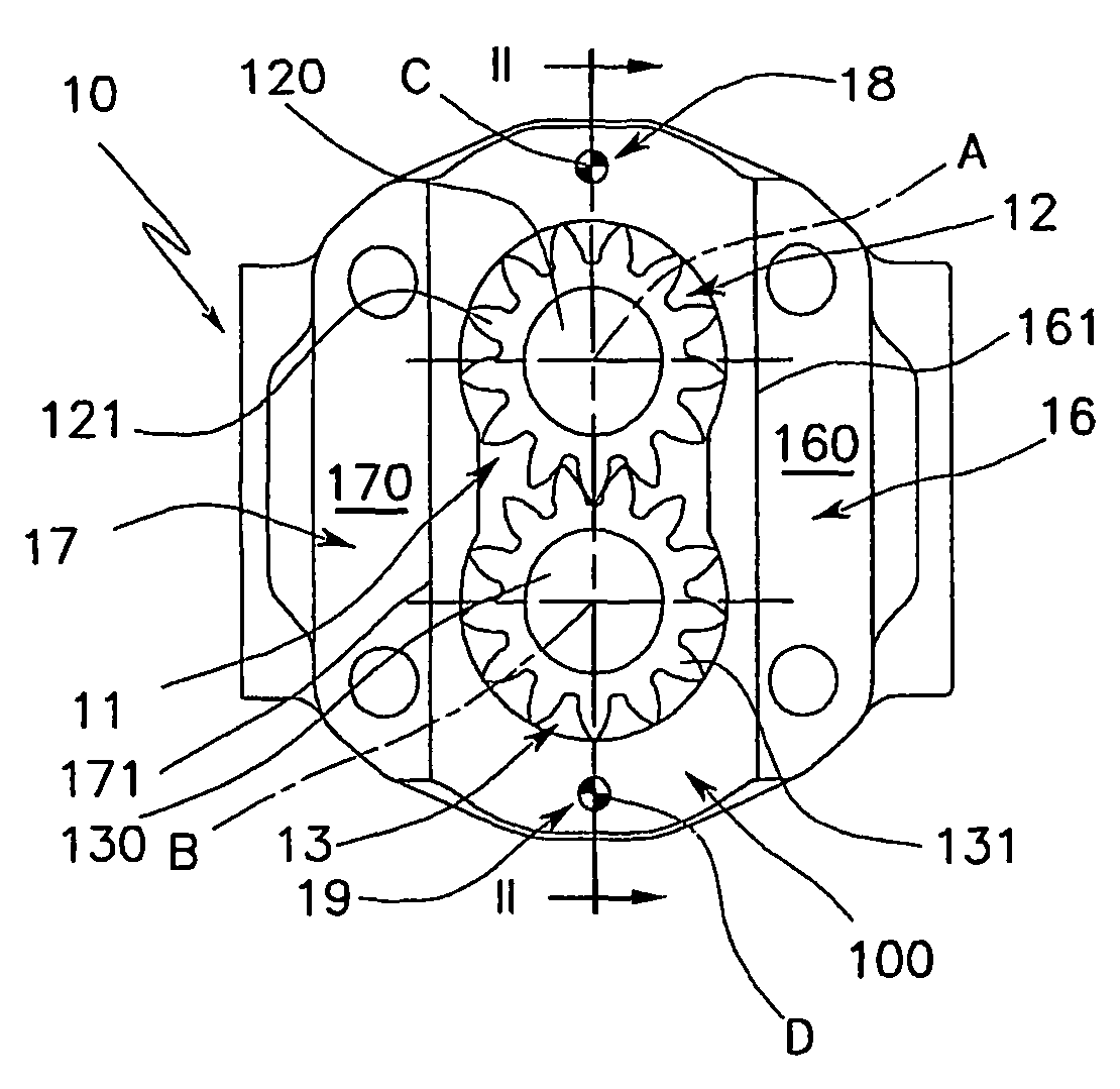
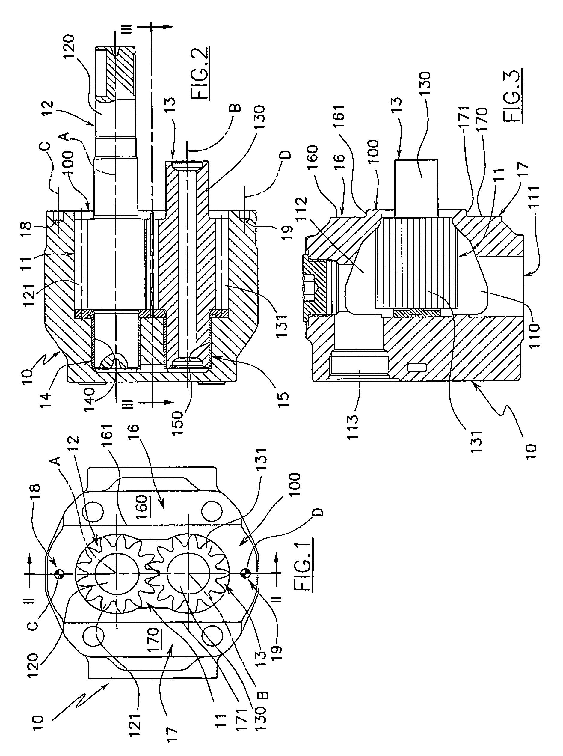
[0061]The hydraulic machine illustrated in FIGS. 7 and 8 comprises a single module 1.

[0062]The module 1 comprises a body 10 which is illustrated in figures from 1 to 3. The body 10 is cup-shaped (see FIG. 2), i.e. it comprises a perimeter wall having an open end and an opposite end which is closed, a bottom wall of which is realised in a single piece with the perimeter wall.

[0063]The body 10 delimits an internal compartment 11 having a transversal section conformed as a figure of 8 (see FIG. 1), which consists in two cylindrical chambers which intersect.

[0064]The longitudinal axes A and B of the cylindrical chambers are parallel to one another and perpendicular to the bottom wall of the body 10.

[0065]The cylindrical chambers are closed by the bottom wall of the body 10, while they are open at the opposite end, where they define the mouth of the compartment 11.

[0066]A gear 12 is snugly contained in one of the cylindrical chambers, which gear enmeshes with a second gear 13 which is sn...


PUM


Abstract

A geared hydraulic machine destined to function as a pump or a motor, comprising at least a module (1) comprising a body (10) in which two chambers are afforded, which two chambers intersect, and each of which contains a gear (12, 13) which enmeshes with a gear (12, 13) contained in the other chamber, the body (10) having at least an open end that is closed by a cover (20) comprising at least a seating (21, 22) for a support bearing (210, 220) of at least a gear (12, 13) of the gears; the coupling between the body (10) and the cover (20) comprises at least two abutments (23, 24) which are fashioned in one of the body (10) and the cover (20), each of which abutments (23, 24) is housed in a respective sunken seating (16, 17) which is afforded in the other of the body (10) and the cover (20).

Description

TECHNICAL FIELD[0001]The invention relates to a geared hydraulic machine of a type designed to function as a pump or as a motor.BACKGROUND ART[0002]As is known, a geared hydraulic machine, whether of the type designed to work as a pump or as a motor, generally comprises a body in which a chamber is afforded having a transversal section conformed as a figure of 8 and consisting of two cylindrical chambers which reciprocally intersect, each of which snugly contains a gear that enmeshes with a gear contained in the other chamber.[0003]The body can be cup-shaped, and thus can comprise a single open end, which is closed by a cover comprising the seatings for the support bearings of the gear shafts; the other support bearing of the shafts of the gears being housed in opposite seatings afforded on the bottom of the cup-shaped body. Alternatively, the body can be substantially tubular with two open opposite ends which are closed by a respective cover, each of which comprises the seatings fo...

Claims


Application Information

Patent Timeline
Patent Type & Authority Patents(United States)
IPC IPC(8): F01C19/10F04C2/18F04C2/08F01C1/24F01C1/18F04C2/00F04C15/00
CPCF04C2/086F04C2/18F04C2240/70F04C2250/00
Inventor MONTIPO', FULVIO
Owner INTERPUMP GRP
Why Eureka
Try Eureka