Light multiplexer

a multiplexer and light technology, applied in the field of light multiplexers, can solve the problems of increasing the coupling loss, the light beam cannot be properly multiplexed or demultiplexed, etc., and achieve the effects of small coupling loss fluctuation, reducing the change of diffraction angle, and reducing the displacement of the grating pitch

Active Publication Date: 2011-06-02
NIPPON TELEGRAPH & TELEPHONE CORP
View PDF6 Cites 0 Cited by
  • Summary
  • Abstract
  • Description
  • Claims
  • Application Information

AI Technical Summary

Benefits of technology

[0017]With this configuration, the diffraction grating is fixed on the side thereof to the supporter via the holder, and further, the heat generated in the substrate is conducted directly to only the supporter since the diffraction grating is not brought into contact with the substrate. As a consequence, although the lower portion of the supporter is displaced by the heat generated in the substrate, an adverse influence of the displacement of the supporter directly on the diffraction grating is reduced since the holder is interposed between the displaced portion and the diffraction grating. In other words, it is possible to reduce the displacement of the diffraction grating influenced by the heat caused by the increase in temperature of the substrate.
[0019]With this configuration, the diffraction grating is configured such that it is held by the holder formed into the simple shape, thereby reducing a production cost.
[0023]With this configuration, when the diffraction grating is held by the holder via an adhesive or soldering, it is possible to prevent a stress from concentrating on the inner corner of the diffraction grating caused by contraction of soldering or the adhesive.
[0032]According to the present disclosure, it is possible to provide the light multiplexer having a small coupling loss fluctuation in which the displacement in grating pitch in the diffraction grating according to the change in temperature can be reduced so as to reduce the change in diffraction angle of the light beam, thus properly multiplexing or demultiplexing the light beam.

Problems solved by technology

In other words, since a grating pitch also is displaced in an X direction according to the displacement, the diffraction angle of the light beam is changed, thereby raising a problem that the light beam cannot be properly multiplexed or demultiplexed.
Consequently, there has arisen a problem that the change in grating pitch in the diffraction grating 5-1 according to the change in temperature increases the coupling loss.

Method used


Image

  • Light multiplexer
  • Light multiplexer
  • Light multiplexer

Examples


first embodiment

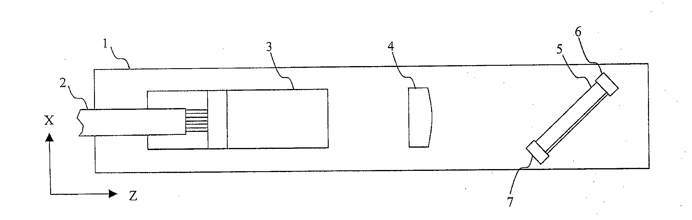
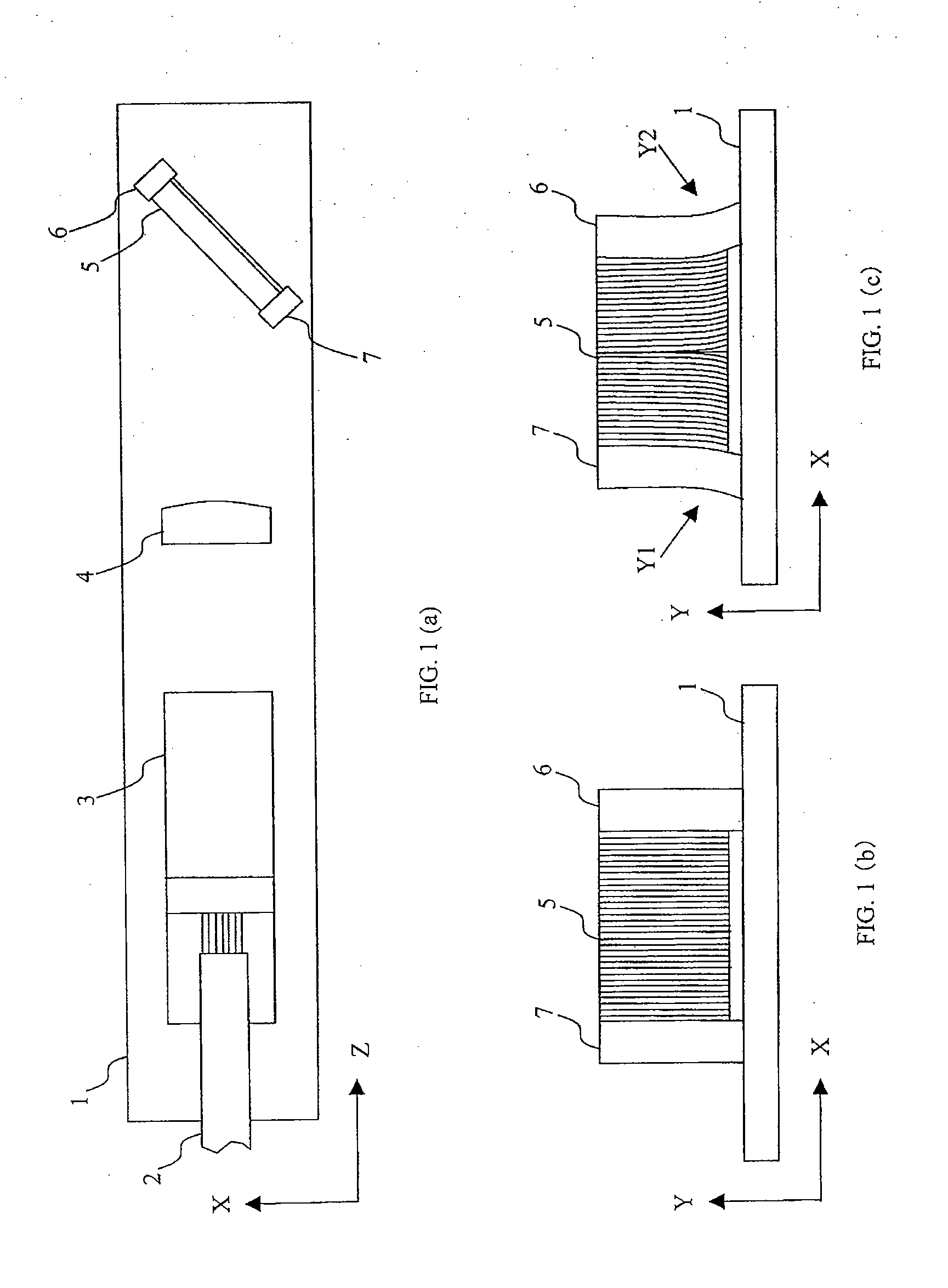
[0044]FIG. 3(a) is a plan view showing the configuration of a light multiplexer of a transmission type in a embodiment according to the present disclosure; FIG. 3(b) is a front view showing the configuration of a diffraction grating, a holder, and supporters on a substrate in the light multiplexer; and FIG. 3(c) is a front view showing the displaced state of the supporters caused by a change in temperature.

[0045]As shown in FIGS. 3(a) to 3(c), a light multiplexer 10 includes, on a substrate 11 made of metal such as Kovar, an optical waveguide input port 12 for emitting a light beam guided by an optical fiber, not shown, from the outside, a lens 13, a transmission type diffraction grating 14 having a plurality of grooves formed in vertical stripes in a glass material such as quartz, a prismatic holder 15 for securely holding one side surface of the diffraction grating 14, a prismatic supporter 16 for securely supporting the holder 15 on the substrate 11, another lens 17, and an optic...

second embodiment

[0058]FIG. 4(a) is a plan view showing the configuration of a light multiplexer of a transmission type in another embodiment according to the present disclosure; FIG. 4(b) is a front view showing the configuration of a diffraction grating, a holder, and supporters on a substrate in the light multiplexer; and FIG. 4(c) is a front view showing the displaced state of the supporters caused by a change in temperature.

[0059]As shown in FIGS. 4(a) to 4(c), a light multiplexer 40 includes, on a substrate 11 made of metal such as Kovar, an optical waveguide input port 12 for emitting a light beam guided by an optical fiber, not shown, from the outside, a lens 13, a transmission type diffraction grating 14 having a plurality of grooves formed in vertical stripes in a glass material such as quartz, a prismatic holder 19 for securely holding the bottom surface of the diffraction grating 14, a prismatic supporter 16 for securely supporting the holder 19 on the substrate 11, another lens 17, and ...

third embodiment

[0072]FIG. 5(a) is a plan view showing the configuration of a light multiplexer of a transmission type in a third embodiment according to the present disclosure; FIG. 5(b) is a front view showing the configuration of a diffraction grating, a holder, and supporters on a substrate in the light multiplexer; and FIG. 5(c) is a perspective view showing the configuration of the diffraction grating, the holder, and the supporters.

[0073]The difference between a light multiplexer 20 in the third embodiment shown in FIGS. 5(a) to 5(c) and the light multiplexer 10 in the first embodiment resides in an L-shaped holder 21 in place of the holder 15.

[0074]Specifically, as shown in FIGS. 5(b) and 5(c), the holder 21 is formed into an L shape, having a bottom 21a parallel to the upper surface of a substrate 11 and a side 21b perpendicular to the bottom 21a, the bottom 21a and the side 21b being welded at an inner corner at right angles. When a diffraction grating 14 is fixed to the holder 21, the co...


PUM


Abstract

One side surface of a diffraction grating is securely held by a holder, and further, the holder is securely supported on a substrate by a supporter in such a manner that the diffraction grating held by the holder is not brought into contact with the substrate. In this manner, the diffraction grating is fixed only onto one side surface to the supporter via the holder, and further, the diffraction grating is not brought into contact with the substrate. Therefore, the lower portion of the supporter is displaced by heat generated in the substrate, however, the displacement of the supporter cannot adversely influence directly on the diffraction grating since the holder is interposed between the displaced portion and the diffraction grating.

Description

BACKGROUND[0001]1. Field of the Disclosure[0002]The present disclosure relates to a light multiplexer provided with a diffraction grating having a plurality of elongated grooves for reflecting or transmitting a light beam, formed on quartz or the like in parallel to each other and, more particularly, to a light multiplexer capable of preventing a grating pitch in a diffraction grating from being changed due to a change in temperature.[0003]2. Discussion of the Background Art[0004]A light multiplexer has a diffraction grating having numerous vertical grooves regularly arranged on a glass substrate in parallel to each other. When light beams are incident into the diffraction grating, the transmitted or reflected light beams are diffracted and interfere with each other, so that only the light beam having a specified wavelength can be taken out. Utilizing this fact, the light multiplexer multiplex or demultiplex the light beams. Here, a diffraction grating for reflecting a light beam is...

Claims


Application Information

Patent Timeline
Patent Type & Authority Applications(United States)
IPC IPC(8): H04J14/00
CPCG02B6/2931G02B6/29311G02B27/1086G02B27/1006G02B7/008G02B7/006
Inventor MITSUHASHI, YUJINISHIZAWA, TOSHIKITOMITA, HIROSHIISHII, YUZOHADAMA, KOICHI
Owner NIPPON TELEGRAPH & TELEPHONE CORP
Why Eureka
Try Eureka