Methods for inverting electromagnetic logging measurements
a technology of electromagnetic logging and inverting, which is applied in the direction of measurement devices, instruments, scientific instruments, etc., can solve the problems of inability to accurately invert the borehole and formation properties, difficulty (or even impossible) in adjusting the logging tool position, and limited computer processing speed, so as to improve the accuracy and reliability of the computed multi-layer formation properties, eliminate errors, and eliminate expensive (and cumbersome) procedures
- Summary
- Abstract
- Description
- Claims
- Application Information
AI Technical Summary
Benefits of technology
Problems solved by technology
Method used
Image
Examples
embodiment 100
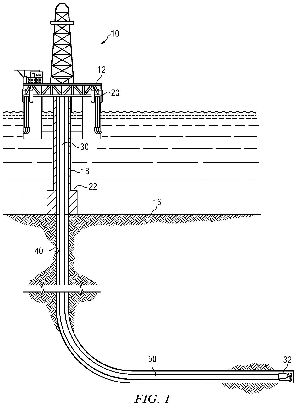
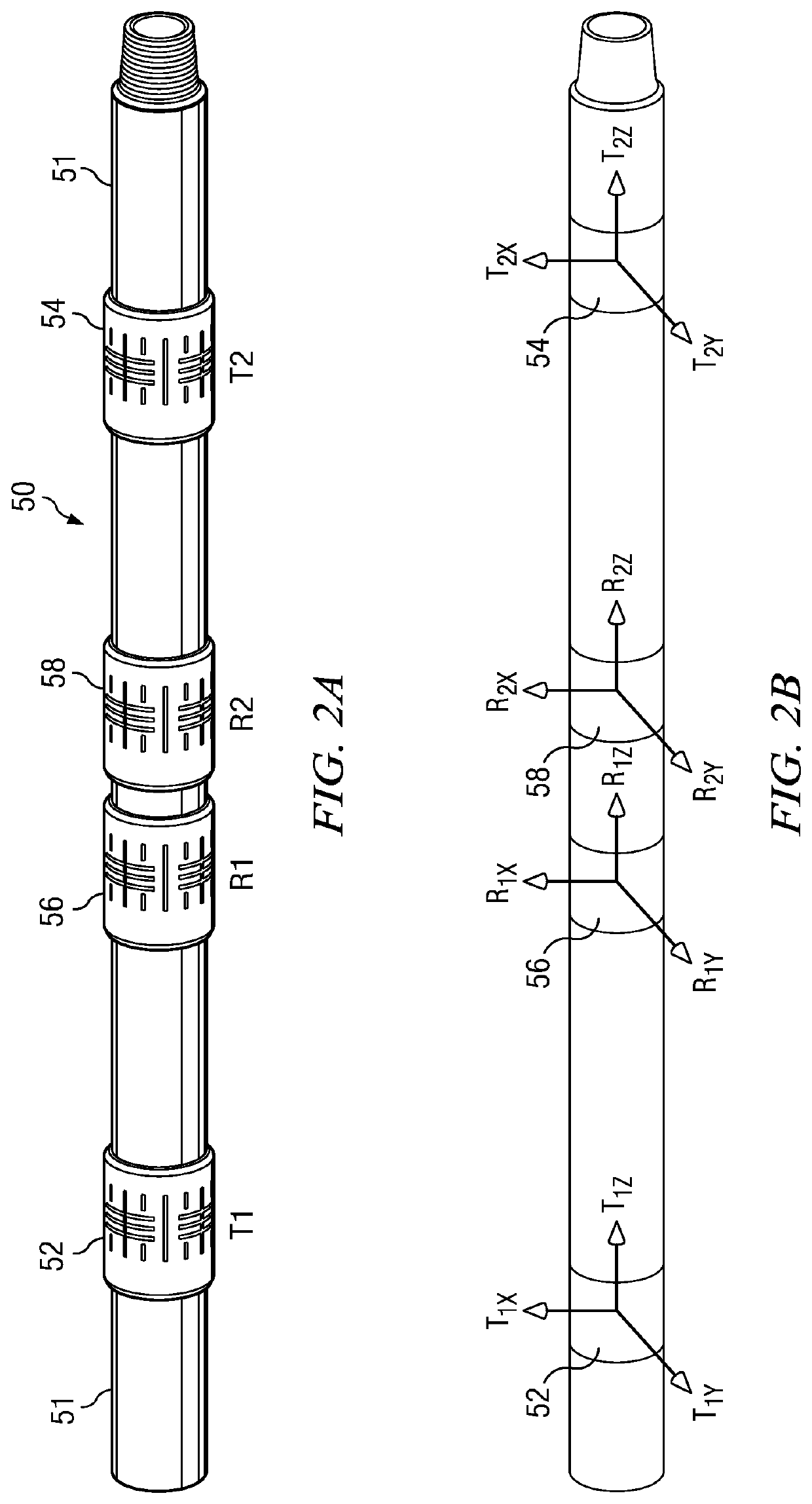
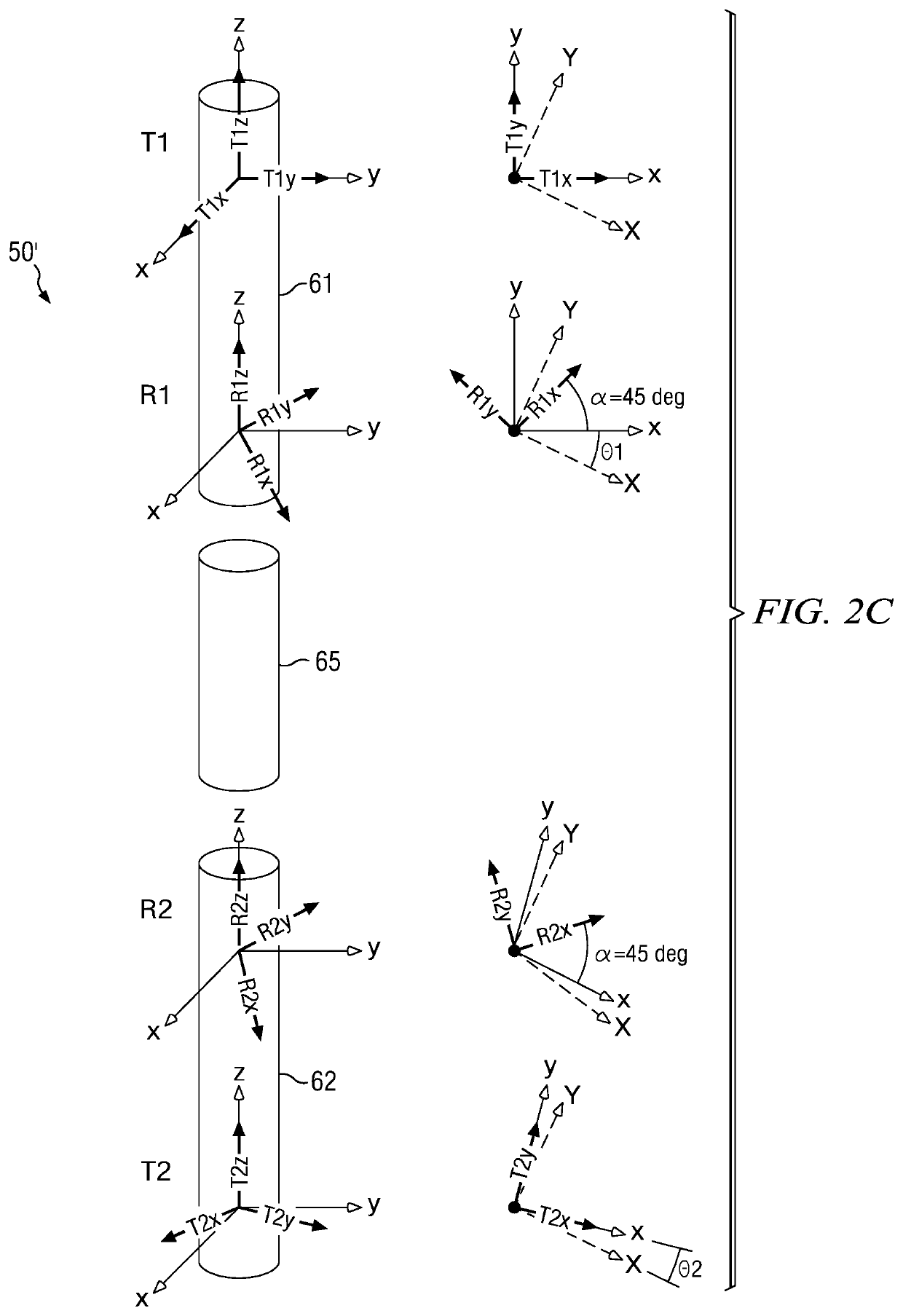
[0034]FIG. 4 depicts a flow chart of one disclosed method embodiment 100 for computing multi-layer formation properties from electromagnetic logging while drilling measurements. An electromagnetic measurement tool (e.g., one of the measurement tools depicted on FIGS. 2B and 2C) is deployed in and rotated in a subterranean wellbore at 102 (e.g., while drilling the wellbore). Electromagnetic measurements are acquired at 104 (e.g., via firing the transmitters and receiving the corresponding electromagnetic waves at the receiving antennas) while the tool is rotating. The electromagnetic measurements are processed at 106 using a first inversion to compute borehole effects (e.g., the effect of the logging tool and the wellbore on the measurements). The borehole effects computed in 106 are then removed from the electromagnetic measurements acquired at 104 (e.g., via subtraction) to compute borehole corrected measurements at 108. The borehole corrected measurements are then processed with a...
embodiment 200
[0066]FIG. 5 depicts a flow chart of another disclosed method embodiment 200 for computing multi-layer formation properties from electromagnetic logging while drilling data. Electromagnetic voltage measurements are acquired at 202 (e.g., while rotating an electromagnetic logging while drilling tool in a wellbore). The measurements are processed at 204 using a first inversion in which the inversion model includes tool details and a uniform (single layer) anisotropic formation to output various formation properties, for example, including horizontal and vertical resistivities, a dip angle, a formation dip azimuth, and various wellbore properties, for example, including a mean decentering distance and a mean decentering azimuth of the tool in the wellbore, a resistivity of the drilling fluid, and the hole diameter. A first set of modeled measurements (e.g., modeled voltage measurements) is computed at 206 using the model (including the tool with finite size antenna coil and conducting ...
embodiment 300
[0068]FIG. 7 depicts a block diagram of another disclosed method embodiment 300 for inverting electromagnetic logging while drilling data to compute multi-layer formation properties. The depicted block diagram may be thought of as including a two-step workflow. In step 1, depicted at 305, the electromagnetic logging data (obtained at 302) is processed to compute and remove borehole effects. In step 2, depicted at 315, the borehole corrected data computed in step 1 is processed using a 1D inversion to compute the multi-layer formation properties.
[0069]Electromagnetic voltage measurements are acquired at a computer processor at 302 (e.g., from an electromagnetic logging while drilling tool that acquired the voltage measurements while rotating in a wellbore as described above). For example, the voltage measurements may be obtained from the logging tool memory upon tripping the tool out of the wellbore or via a high bandwidth communication link (such as wired drill pipe) between the log...
PUM
 Abstract
Description
Claims
Application Information
 - R&D
- Intellectual Property
- Life Sciences
- Materials
- Tech Scout
- Unparalleled Data Quality
- Higher Quality Content
- 60% Fewer Hallucinations
Browse by: Latest US Patents, China's latest patents, Technical Efficacy Thesaurus, Application Domain, Technology Topic, Popular Technical Reports.
© 2025 PatSnap. All rights reserved.Legal|Privacy policy|Modern Slavery Act Transparency Statement|Sitemap|About US| Contact US: help@patsnap.com


