Kiln and heating method thereof

a technology which is applied in the field of kiln and heating method, can solve the problems of easy falling of ashes generated from burning wood, difficult control of cavity temperature, polluting food ingredients, etc., and achieve the effects of preventing heat conductivity, improving heating efficiency, and reducing the time of cooking good ingredients

Active Publication Date: 2021-02-16
NAT CHUNG SHAN INST SCI & TECH +1
View PDF6 Cites 1 Cited by
  • Summary
  • Abstract
  • Description
  • Claims
  • Application Information

AI Technical Summary

Benefits of technology

[0015]The advantage of the present invention is that a dual heating effect could be achieved by utilizing the open fire and the infrared ray generated by the combustion device, and the heating efficiency could be improved by forming the over-heated steam and the structural design of the stove as well, whereby a cooking time for the good ingredients could be shortened. In addition, the isolation space could provide a thermal insulation effect, which could prevent heat conducting from the stove to the housing so as to avoid the user from being burned when the user accidentally touches the housing.
is that a dual heating effect could be achieved by utilizing the open fire and the infrared ray generated by the combustion device, and the heating efficiency could be improved by forming the over-heated steam and the structural design of the stove as well, whereby a cooking time for the good ingredients could be shortened. In addition, the isolation space could provide a thermal insulation effect, which could prevent heat conducting from the stove to the housing so as to avoid the user from being burned when the user accidentally touches the housing.

Problems solved by technology

Since the wood and the food ingredients are placed into the same space, the ashes generated from burning the wood are easily fallen onto the food ingredients to pollute the food ingredients.
Furthermore, when the wood is used as a heat source, the temperature of the cavity is not easy to control and the heating efficiency thereof is low.
Therefore, it is usually seen that the surface of the food ingredient has been burnt but the inside of the food ingredient is not yet cooked.
If a user accidentally touches a front side of the stove in the operation process, it is possible that the user would get burned.

Method used


Image

  • Kiln and heating method thereof
  • Kiln and heating method thereof
  • Kiln and heating method thereof

Examples


Embodiment Construction

[0033]The following illustrative embodiments and drawings are provided to illustrate the inventive subject matter, its advantages and effects so that it can be clearly understood by persons skilled in the art after reading the disclosure of this specification.

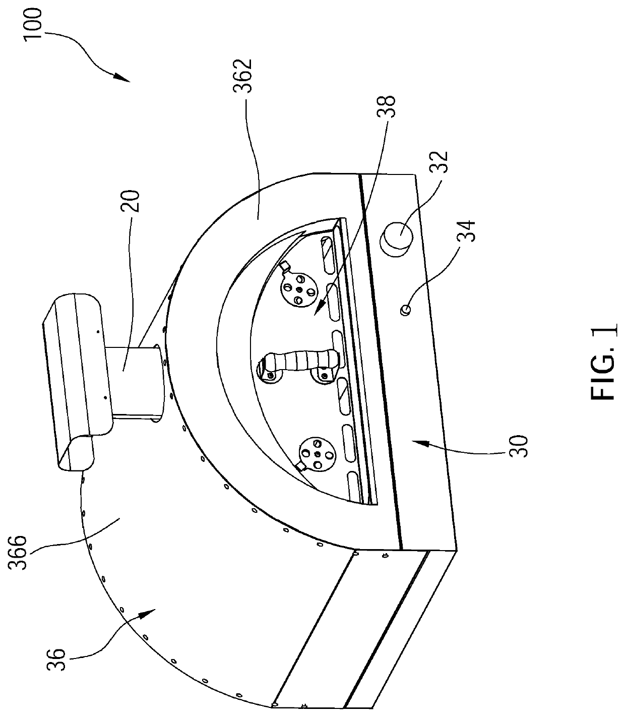
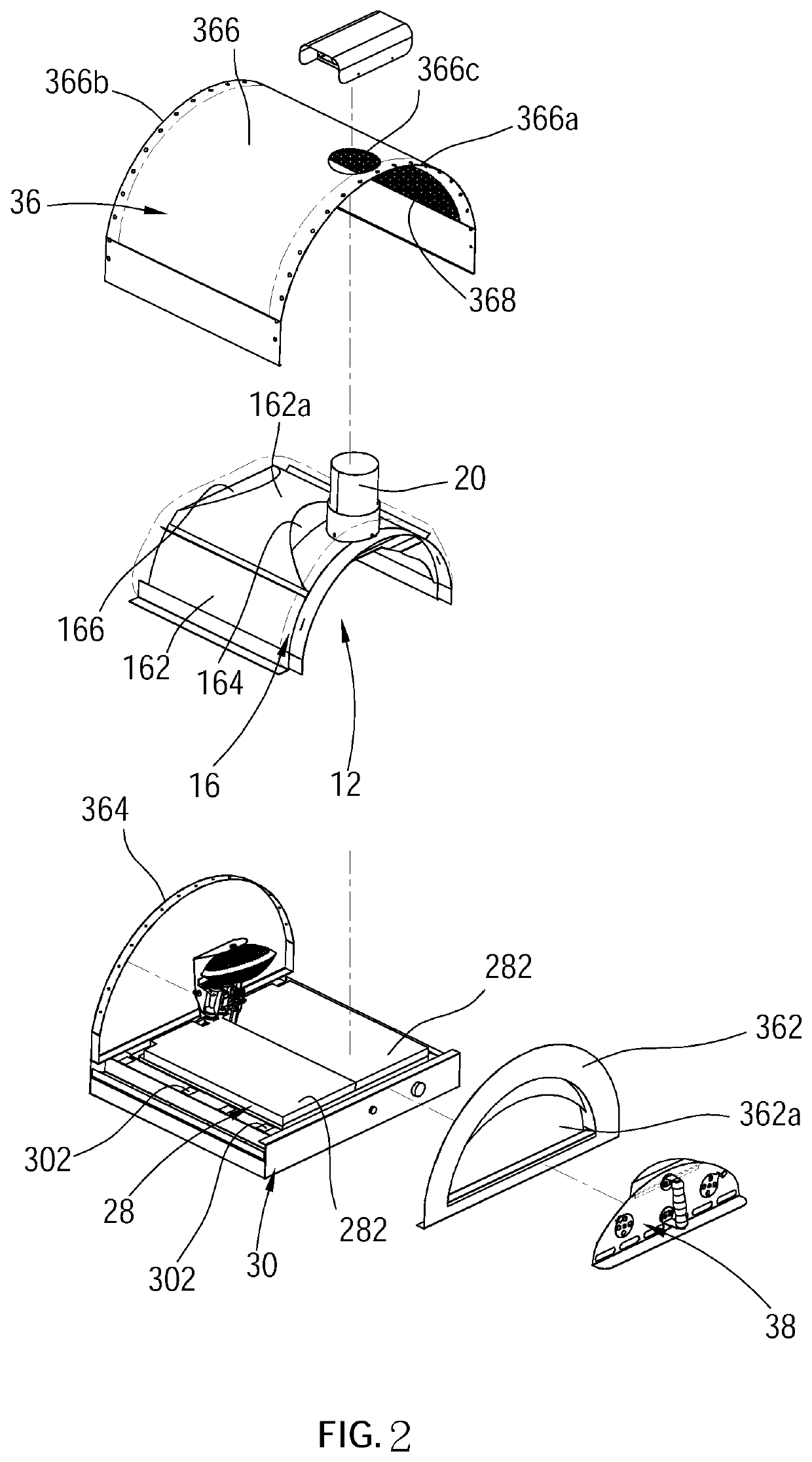
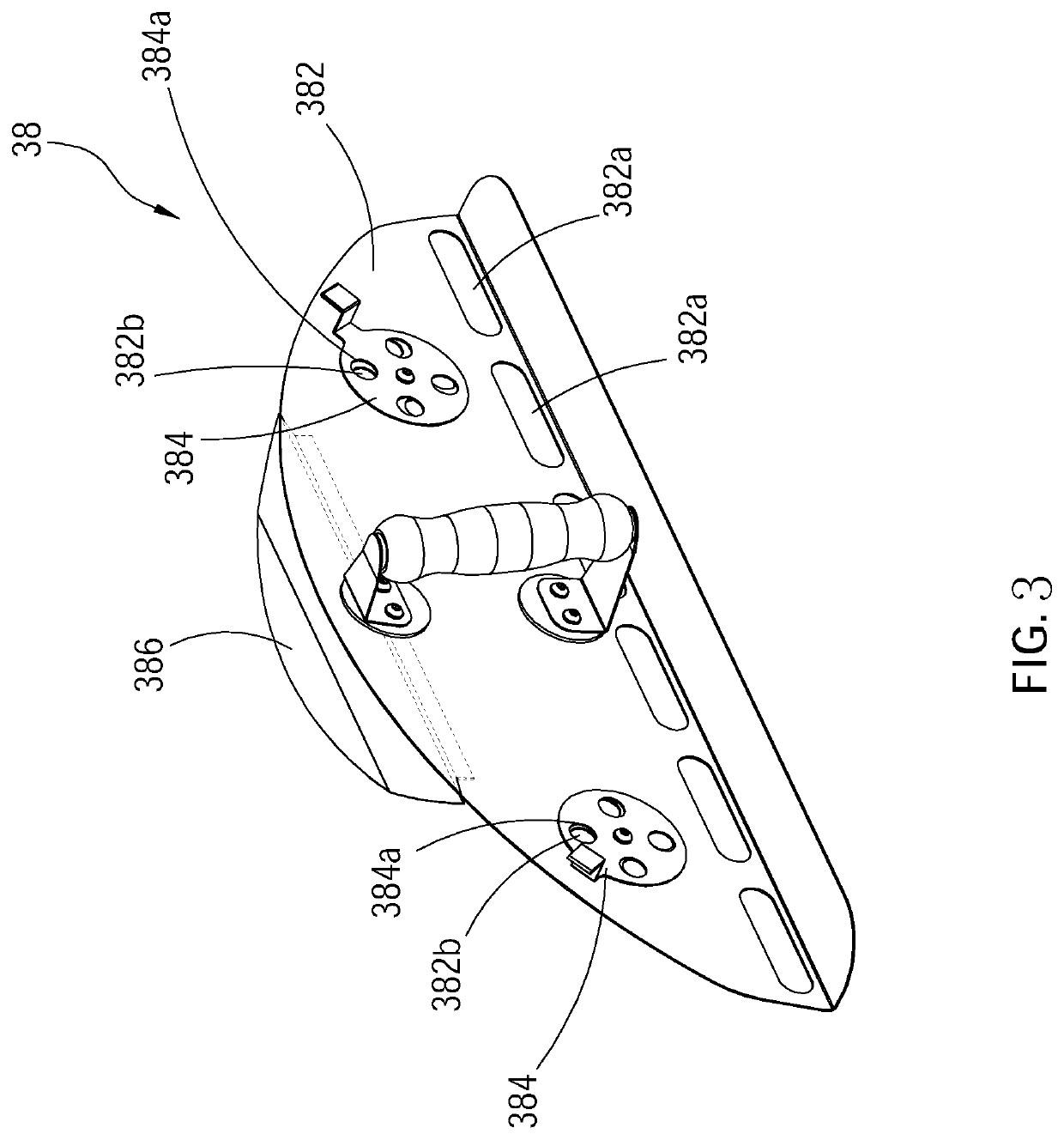
[0034]As illustrated in FIG. 1 to FIG. 10, a kiln 100 of a first embodiment according to the present invention includes a stove 10, a housing 36, a door 38, and a heat source which is a combustion device 40 as an example.

[0035]The stove 10 includes a cavity 12 and an entry 14. Wherein, the cavity 12 includes a front section 122 and a rear section 124. The front section 122 communicates with the entry 14, and a top wall surface at the front section 122 tilts toward the entry 14 downwardly. The rear section 124 is away from the entry 14. An inner wall surface 124a is located at the rear section 124 and faces the entry 14. A top wall surface at the rear section 124 tilts upwardly in a direction away from the inner wall surface 124...


PUM


Abstract

A kiln includes a stove, a combustion device, and an exhaust pipe, wherein the stove includes a cavity, an entry, and an air outlet. The cavity includes a front section and a rear section, and a top wall surface of the front section is tilt. The air outlet is disposed between a top of the front section of the cavity and the entry. The combustion device is disposed in the rear section. The combustion device includes at least one burner, a supporting assembly, and an infrared ray generation assembly. The supporting assembly includes a cover plate having a hollow portion. The infrared ray generation assembly is mounted to the supporting assembly and located above the cover plate. The infrared ray generation assembly could be heated by the flames of the burner to generate infrared ray which passes through the hollow portion. The exhaust pipe communicates with the air outlet.

Description

BACKGROUND OF THE INVENTION1. Technical Field[0001]The present invention is related to a heating apparatus, and more particularly to a kiln which burns gas to generate heat and a heating method thereof.2. Description of Related Art[0002]Conventional kilns are adapted for cooking food, such as baking pizza, roasting chicken, stewing vegetables, etc. The stove of conventional kilns is usually built by stacking stone material, and an entry is formed at the front side of the stove to communicate with an inside of the cavity. During the stove is in use, wood is added into the cavity from the entry and then the wood is burned to heat the cavity. When the cavity is heated to a temperature suitable for baking food, food ingredients are placed into the cavity from the entry so as to cook the food.[0003]Since the wood and the food ingredients are placed into the same space, the ashes generated from burning the wood are easily fallen onto the food ingredients to pollute the food ingredients. F...

Claims


Application Information

Patent Timeline
Patent Type & Authority Patents(United States)
IPC IPC(8): F24C3/00F24C3/04F24C15/30F24C3/08A21B1/28F24B1/24A21B1/02
CPCF24C3/042A21B1/02A21B1/28F24B1/24F24C3/004F24C3/082F24C15/30A47J37/0623A47J37/0647A47J37/0652A47J37/0658A47J37/0664
Inventor TSENG, HSI-MINGLIAO, LI-CHIH
Owner NAT CHUNG SHAN INST SCI & TECH
Why Eureka
Try Eureka