
Internal battery thermal management system for secondary batteries

a battery thermal management and secondary battery technology, applied in secondary cell servicing/maintenance, nickel accumulators, sustainable manufacturing/processing, etc., can solve the problems of accelerating capacity fading, working well, and degrading battery performan

Active Publication Date: 2021-02-09
LIU JIE
View PDF10 Cites 0 Cited by
  • Summary
  • Abstract
  • Description
  • Claims
  • Application Information

AI Technical Summary

Benefits of technology

This approach enhances temperature uniformity and cooling efficiency within the battery cell, allowing for a lightweight, cost-effective PCM-based internal thermal management system that maintains high latent heat without the need for expanded graphite, thus improving battery performance and lifespan.

Problems solved by technology

However, the temperature sensitivity of Li-ion batteries makes them work well only in a certain temperature range.
A low temperature (e.g., lower than 0° C.) or a high temperature (e.g., higher than 50° C.) can degrade the battery performance, and even accelerate the capacity fading.
An active BTM system dissipates the heat generated from batteries by circulating the cooling air or coolant, and it generally needs a power-consuming device, such as a pump or a cooling fan, to circulate the cooling medium.
Active BTM system is efficient in managing the battery temperature, but it consumes part of the battery energy, and it adds complexities to the system.
Amongst the drawbacks of passive BTM systems is that the addition of the cooling material increases the weight of the battery system and reduces the volume of active charge storing material, thus reducing the specific energy of the battery system.
However, within the prior art it has been identified that the low thermal conductivity of the PCM or PCMs employed can substantially constrain its actual cooling potential.
In addition, PCMs are liquid materials which adds extra complexity to the BTM system.
% EG thereby lowers the latent heat of entire BTM system as well as increasing the manufacturing cost.

Method used


Image

  • Internal battery thermal management system for secondary batteries
  • Internal battery thermal management system for secondary batteries
  • Internal battery thermal management system for secondary batteries

Examples


Embodiment Construction

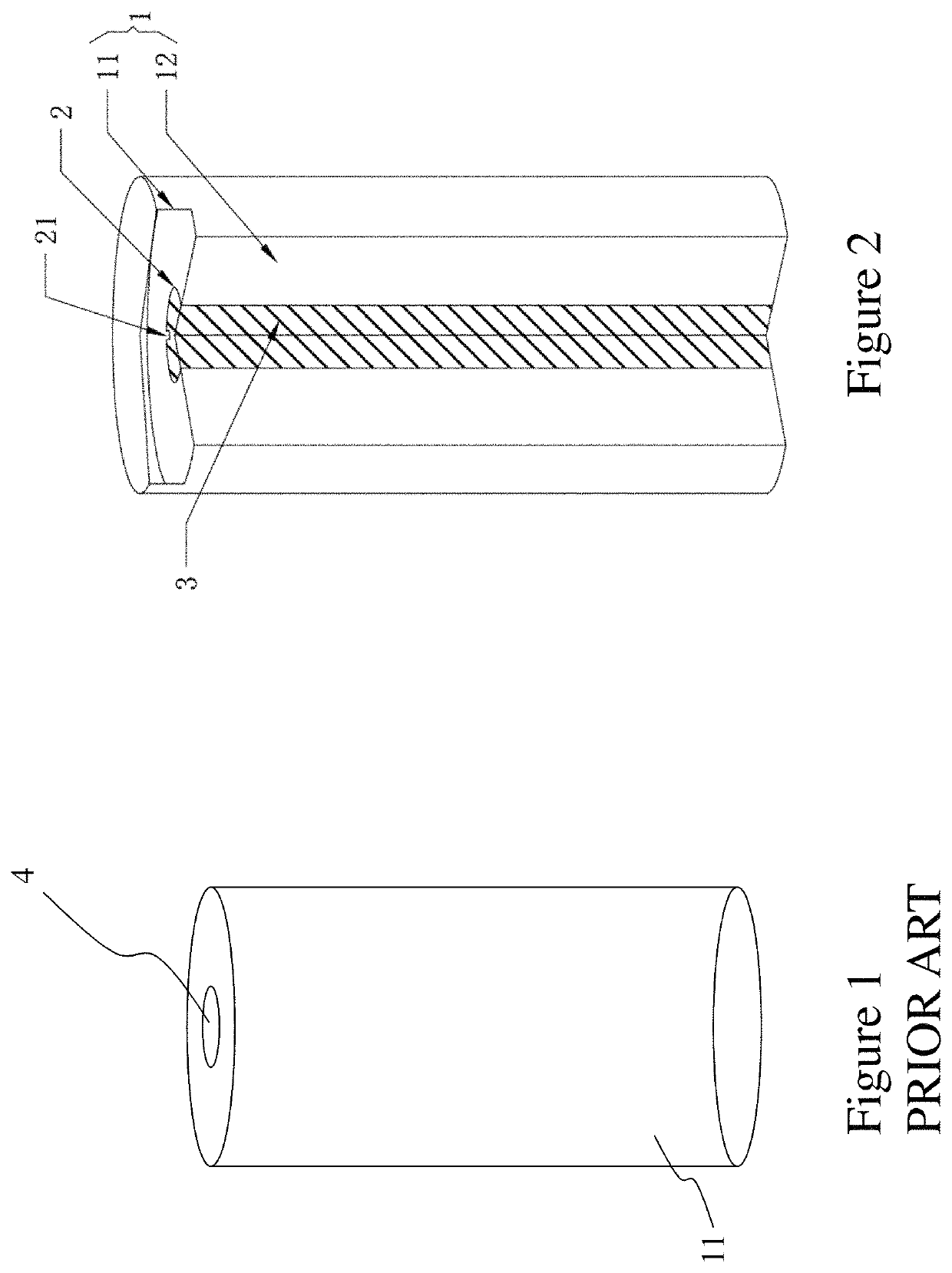
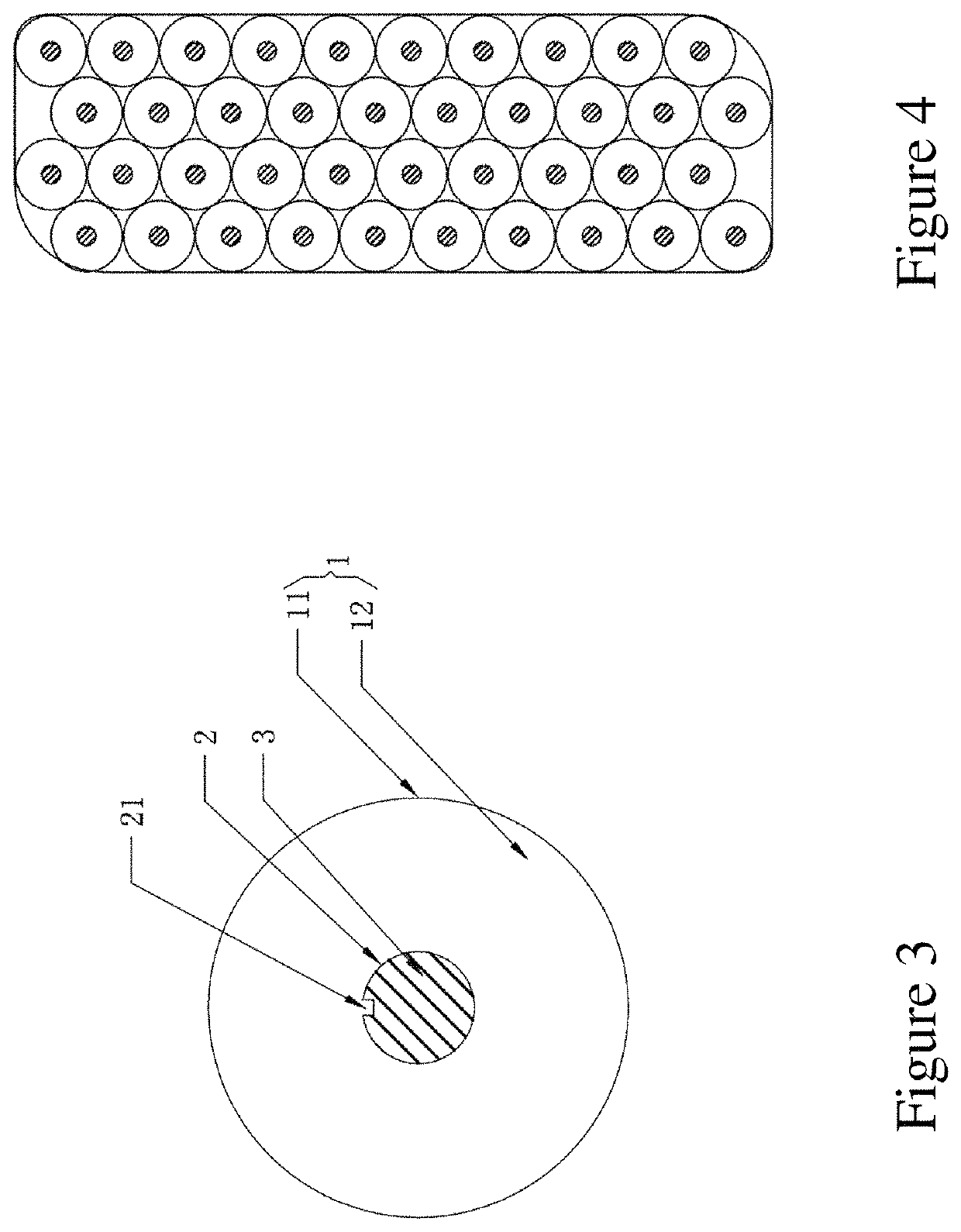
[0029]The present description is directed to batteries and more particularly to methods and systems for battery thermal management field, and more specifically, phase change material based internal thermal management system for secondary batteries.

[0030]The ensuing description provides representative embodiment(s) only, and is not intended to limit the scope, applicability or configuration of the disclosure. Rather, the ensuing description of the embodiment(s) will provide those skilled in the art with an enabling description for implementing an embodiment or embodiments of the invention. It being understood that various changes can be made in the function and arrangement of elements without departing from the spirit and scope as set forth in the appended claims. Accordingly, an embodiment is an example or implementation of the inventions and not the sole implementation. Various appearances of “one embodiment,”“an embodiment” or “some embodiments” do not necessarily all refer to the...


PUM

PropertyMeasurementUnit
temperatureaaaaaaaaaa
maximum temperatureaaaaaaaaaa

Abstract

A low temperature (e.g., lower than 0° C.) or a high temperature (e.g., higher than 50° C.) can degrade battery performance, especially within lithium ion (Li-ion) batteries, and even accelerate the capacity fading. To ensure a long term and safe operation of Li-ion batteries, the battery thermal management (BTM) system becomes a crucial part to control the temperature of each discrete battery or every battery within a battery pack. Within the prior art a phase change material (PCM) has been employed combined with a graphite matrix. However, the graphite lowers the latent heat of entire BTM system and increases the manufacturing cost. Embodiments of the invention provide sealed mandrels or elements which immobilize the PCM without impacting the latent heat of the entire BTM system and increasing manufacturing costs.

Description

FIELD OF THE INVENTION[0001]This patent application relates to batteries and more particularly to methods and systems for battery thermal management field, and more specifically, phase change material based internal thermal management system for secondary batteries.BACKGROUND OF THE INVENTION[0002]Secondary batteries, especially lithium-ion (Li-ion) batteries, are extensively used in daily life. Due to their high energy density, specific energy, and low capacity fading rate, Li-ion batteries have become an indispensable component for the electric vehicle (EV) and hybrid electric vehicle (HEV) market. They are also used in a wide range of portable electronic devices such as cellphones, power banks, laptops, digital cameras, gaming consoles, etc. as well as a wide range of fixed electronic devices as a backup to the primary wired power supply (commonly referred to as mains) when this fails. There are a variety of types of secondary batteries, including lithium-ion (Li-ion) batteries (...

Claims


Application Information

Patent Timeline
Patent Type & Authority Patents(United States)
IPC IPC(8): H01M10/637H01M10/0525H01M10/615H01M10/42H01M10/48H01M10/6571H01M10/654H01M10/6551H01M10/659H01M2/10H01M10/0585H01M10/0587H01M50/204
CPCH01M10/637H01M2/1016H01M10/0525H01M10/0585H01M10/0587H01M10/425H01M10/486H01M10/615H01M10/654H01M10/659H01M10/6551H01M10/6571H01M2010/4278H01M10/633H01M50/204H01M10/443H01M10/30H01M10/345Y02E60/10Y02P70/50
Inventor LIU, JIEZHAO, RUI
Owner LIU JIE
Learn More