
Method for vacuum smelting and variable pressure solidification forming aluminum alloy piece with ultra-thin wall and high gas tightness

a technology of vacuum smelting and variable pressure solidification, which is applied in the field of aluminum alloy manufacturing, can solve the problems of patent application not performing improvement and control on smelting time, high mold-filling, and difficulty in prior art to ensure product quality of ultra-thin-walled duct products requiring high cleanliness, etc., and achieves high air tightness, avoids the cost of smelting protection, and high purity argon

Active Publication Date: 2021-02-09
NO 59 RES INST OF CHINA ORDNANCE IND
View PDF4 Cites 0 Cited by
  • Summary
  • Abstract
  • Description
  • Claims
  • Application Information

AI Technical Summary

Benefits of technology

The present invention provides a method for vacuum smelting and variable pressure solidification forming aluminum alloy piece with ultra-thin wall and high gas tightness. This method has the advantages of high melting efficiency, less oxidation inclusion, and compact working procedure. The method is simple in operation and high in integration degree, easy to be widely used in industrial production. The use of a thin-wall and the densification of microstructure are considered, and the mold-filling effect of the thin-wall is ensured to be well filled and the solidification pressure of the castings is increased. The aluminum alloy casting manufactured by this method has high quality, is cost-effective, and can be widely used in aerospace field.

Problems solved by technology

In the prior art, although there are technologies and methods for vacuum smelting and vacuum casting of aluminum alloy, it is difficult for the prior art to ensure product quality for ultra-thin-walled duct products requiring high cleanliness, low casting amount of one time and high mold-filling.
However, this patent application does not perform improvement and control on the smelting time.
In a case where the ultra-thin-walled aluminum alloy duct is produced by this method, because the casting mold is small, the is temperature of the casting mold is decreased rapidly after the casting mold is transferred from the roasting furnace to the vacuum tank; If the smelting time is not well controlled, the temperature of the casting mold will be too low due to a long time smelting, thereby reducing the mold-filling effect.
In addition, the solidification pressure in this patent application is normal pressure, so it is difficult to ensure the air tightness of the casting of which the interior bears pressure.
For the melt of aluminum alloy with a density of 2.5 g / cm3, this pressure may result in that the melt is in a high-speed flow state, which is not suitable for the pouring formation of small thin-walled castings.
In addition, the second crucible in this method only supports flowing into the cavity of the casting mold under the action of gravity, which cannot guarantee the completion of pouring of all the alloy melt during pouring process every time.
Moreover, the sealing and liquid transfer mechanisms in the second crucible is complicated, which is not conducive to the cleaning of the crucible after pouring every time, thereby easily leading to the contamination of the alloy melt during the second time of pouring.
(1) It is difficult for the prior art to ensure product quality for ultra-thin-walled duct products requiring high cleanliness, low casting amount of one time and high mold-filling.
(2) The temperature of the casting mold will be too low due to the long time smelting process, thereby reducing the mold-filling effect.
In addition, the solidification pressure is normal pressure, so it is difficult to ensure the air tightness of the casting of which the interior bears pressure.
(3) The melt is in a high-speed flow state, which is not suitable for the pouring formation of small thin-walled castings.
Moreover, it cannot guarantee the completion of pouring of all the alloy melt because of the gravity casting, and it is not conducive to the cleaning of the crucible due to the complicated mechanisms of the crucible, thereby easily leading to the contamination of the alloy melt during the second time of pouring.
Difficulty and significance of solving the above technical problems:

Method used


Image

  • Method for vacuum smelting and variable pressure solidification forming aluminum alloy piece with ultra-thin wall and high gas tightness
  • Method for vacuum smelting and variable pressure solidification forming aluminum alloy piece with ultra-thin wall and high gas tightness

Examples


first embodiment

ZL101A Aluminum Alloy

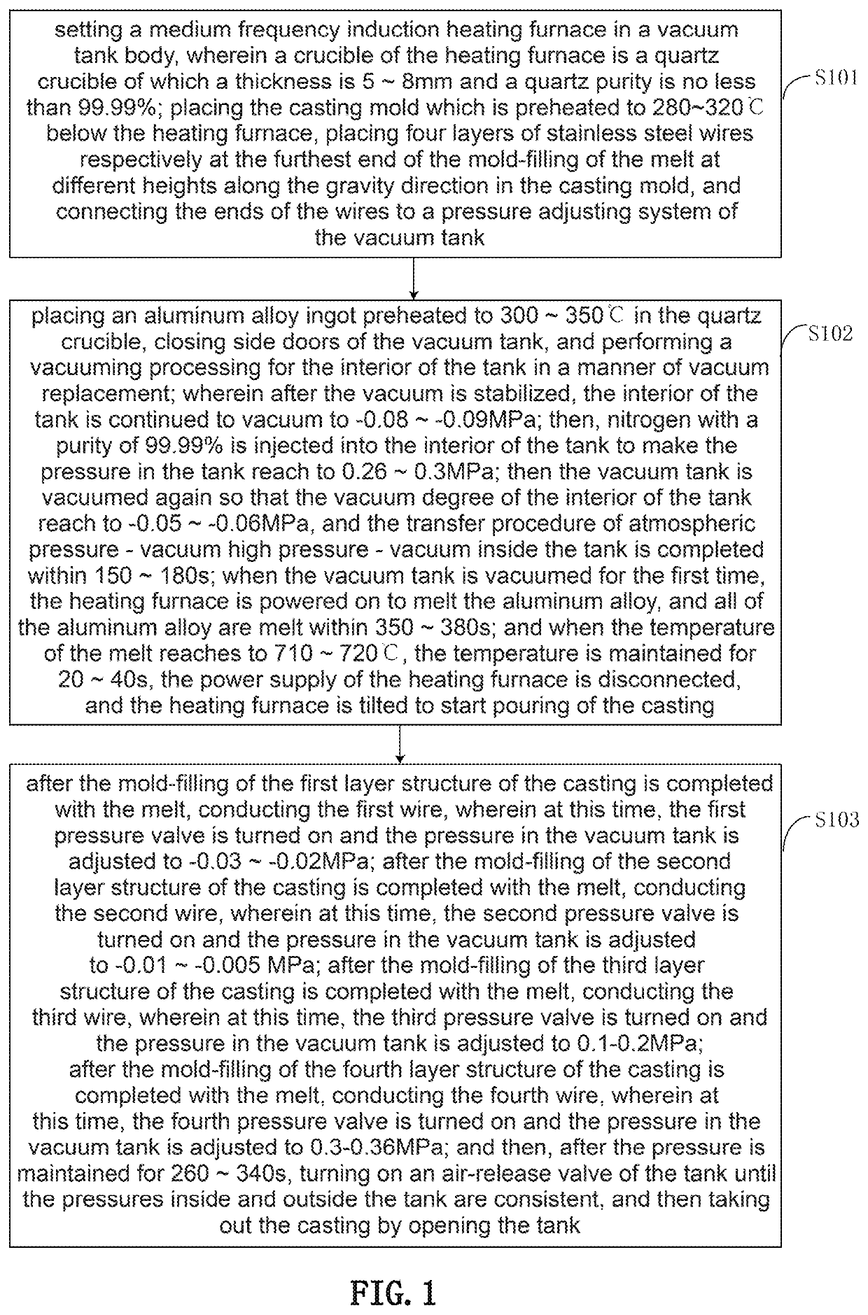
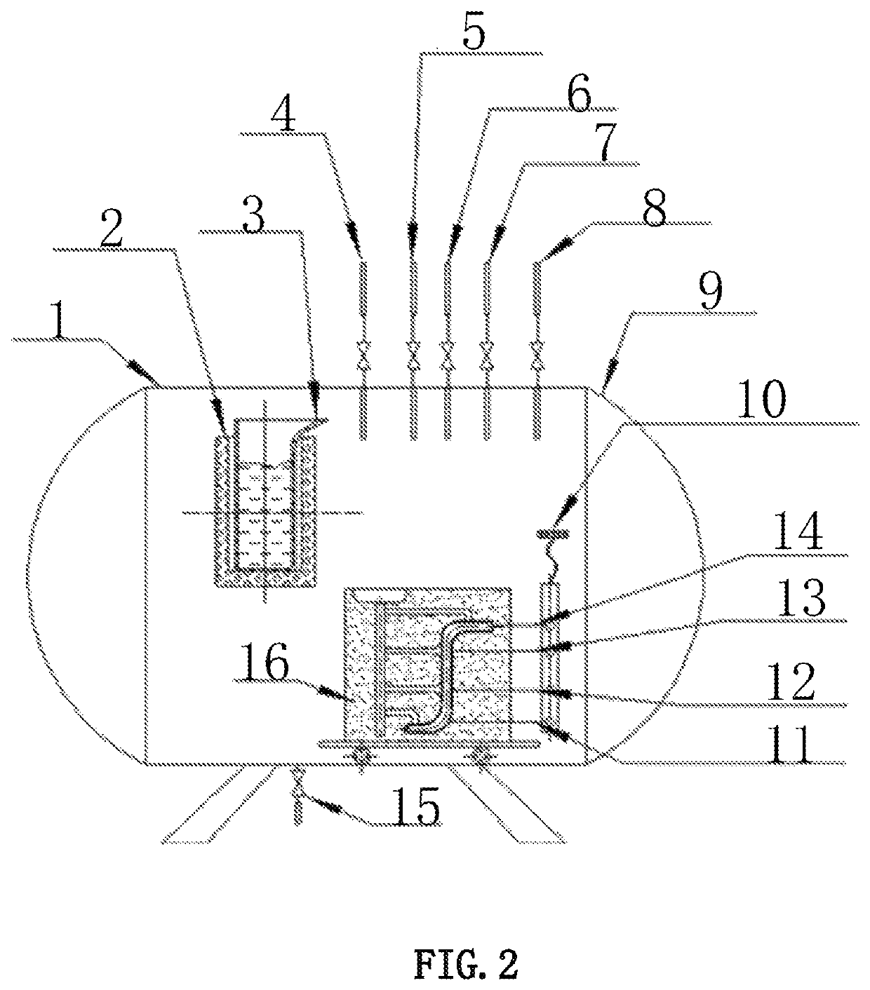
[0046]1. A medium frequency induction heating furnace is set in a vacuum tank body, and a quartz crucible of which the thickness is 5 mm is used as a crucible of the heating furnace and a quartz purity is no less than 99.99%; the casting mold which is preheated to 305° C. is placed below the heating furnace, four layers of stainless steel wires are respectively placed at the furthest end positions of the mold-filling of the melt at different heights along the gravity is direction in the casting mold, and the ends of the wires are connected to a pressure adjusting system of the vacuum tank.

[0047]2. An aluminum alloy ingot preheated to 300° C. is placed in the quartz crucible, side doors of the vacuum tank is closed, and a vacuuming processing is performed for the interior of the tank in a manner of vacuum replacement; after the vacuum is stabilized, the interior of the tank is continued to vacuum to −0.09 MPa; then, nitrogen with a purity of 99.99% is injected in...

second embodiment

L114A Aluminum Alloy

[0050]1. A medium frequency induction heating furnace is set in a vacuum tank body, and a quartz crucible of which a thickness is 7 mm is used as a crucible of the heating furnace and a quartz purity is no less than 99.99%; the casting mold which is preheated to 280° C. is placed below the heating furnace, four layers of stainless steel wires are respectively placed at the furthest end positions of the mold-filling of the melt at different heights along the gravity direction in the casting mold, and the ends of the wires are connected to a pressure adjusting system of the vacuum tank.

[0051]2. An aluminum alloy ingot preheated to 332° C. is placed in the quartz crucible, side doors of the vacuum tank is closed, and a vacuuming processing is performed for the interior of the tank in a manner of vacuum replacement; after the vacuum is stabilized, the interior of the tank is continued to vacuum to −0.08 MPa; then, nitrogen with a purity of 99.99% is injected into the...

third embodiment

ZL205A Aluminum Alloy

[0054]1. A medium frequency induction heating furnace is set in a vacuum tank body, and a quartz crucible of which a thickness is 8mm is used as a crucible is of the heating furnace and a quartz purity is no less than 99.992%; the casting mold which is preheated to 320° C. is placed below the heating furnace, four layers of stainless steel wires are respectively placed at the furthest end positions of the mold-filling with the melt at different heights along the gravity direction in the casting mold, and the ends of the wires are connected to a pressure adjusting system of the vacuum tank.

[0055]2. An aluminum alloy ingot preheated to 350° C. is placed in the quartz crucible, side doors of the vacuum tank is closed, and a vacuuming processing is performed for the interior of the tank in a manner of vacuum replacement; after the vacuum is stabilized, the interior of the tank is continued to vacuum to −0.086 MPa; then, nitrogen with a purity of 99.99% is injected i...


PUM

PropertyMeasurementUnit
thicknessaaaaaaaaaa
temperatureaaaaaaaaaa
densityaaaaaaaaaa

Abstract

A method for vacuum smelting and variable pressure solidification forming aluminum alloy piece with ultra-thin wall and high gas tightness is provided, in which an induction heating furnace is set in a vacuum tank, a quartz crucible with thickness of 5˜8 mm is used; a preheated aluminum alloy ingot is placed in the crucible, side doors of the tank is closed, and a vacuuming processing is performed for the tank; the melt is filled from the bottom layer of the casting; when the melt reaches to the top, the main valve and the air-release valve are turned on until the inside and outside pressures are consistent, and then the casting is taken out. The requirement of high air tightness for vacuum tank is reduced, and aluminum alloy casting with high quality can be obtained at lower cost.

Description

CROSS REFERENCE TO RELATED APPLICATIONS[0001]The present application claims priority to Chinese Patent Application No. 201910298554.7 filed on Apr. 15, 2019, the entire content of which are incorporated herein by reference.FIELD OF THE INVENTION[0002]The present invention relates to a technical field of aluminum alloy is manufacturing, particularly to a method for vacuum smelting and variable pressure solidification forming aluminum alloy piece with ultra-thin wall and high gas tightness.BACKGROUND[0003]With the increasing demand for weight reduction in aerospace industry, aluminum alloy castings are developing towards a tendency of thin wall and ultra-thin wall. For ultra-thin-walled aviation duct products with gas tightness requirements, because they present bending and variable section characteristics in three-dimensional direction, it is generally necessary to adopt an investment casting process and complete smelting and pouring procedure under vacuum so to ensure its low oxidat...

Claims


Application Information

Patent Timeline
Patent Type & Authority Patents(United States)
IPC IPC(8): B22D27/15B22D18/06
CPCB22D27/15B22D18/06B22D37/00B22D27/13
Inventor CHEN, QIANGWAN, YUANYUANXING, ZHIHUITAO, JIANQUANZHAO, GAOZHANHUANG, ZHIWEILI, MINGLI, XIAOSONGCHAI, SHUXINWANG, YANBINZHAN, HONGWANG, MAOCHUAN
Owner NO 59 RES INST OF CHINA ORDNANCE IND
Learn More