
Sawtooth structure with reversed cutting function and its drill series

a sawtooth structure and function technology, applied in the field of drills, can solve the problems of weak bonding between two adjacent laminates, rapid tool wear, and dull cutting edges

Active Publication Date: 2020-12-08
BLUEDRILL TECH SHENZHEN CO LTD
View PDF16 Cites 1 Cited by
  • Summary
  • Abstract
  • Description
  • Claims
  • Application Information

AI Technical Summary

Benefits of technology

This invention solves a problem where defects such as delamination, burrs, and cracks easily form at the exit and entrance of drilling fiber reinforced composites. The invention is a sawtooth structure with reverse cutting function, which can be applied to various drilling tools. The sawtooth structure helps to rebound the uncut materials back into it in different working conditions, which prevents burrs and delamination and improves the cutting ability of the drill.

Problems solved by technology

Because CFRP is comprised of carbon fiber reinforcement and resin matrix, the material is anisotropic and stacked, and the bonding between two adjacent laminates is weak.
At the same time, the extremely abrasive carbon fiber can cause rapid tool wear and thus dull the cutting edges, which leads to difficulties in cutting off carbon fibers and subsequent burrs at hole entrance and hole exit.
However, fiber pullouts are easily generated, and tool wear occurs rapidly in drilling laminated materials with low bonding.
And severe tool wear can lead to significant quality drop of drilled holes.
The specially designed twist drill can reduce delamination to a certain extent, however, the tool life is relatively short thus leading to burrs rapidly.

Method used


Image

  • Sawtooth structure with reversed cutting function and its drill series
  • Sawtooth structure with reversed cutting function and its drill series
  • Sawtooth structure with reversed cutting function and its drill series

Examples


embodiment 1

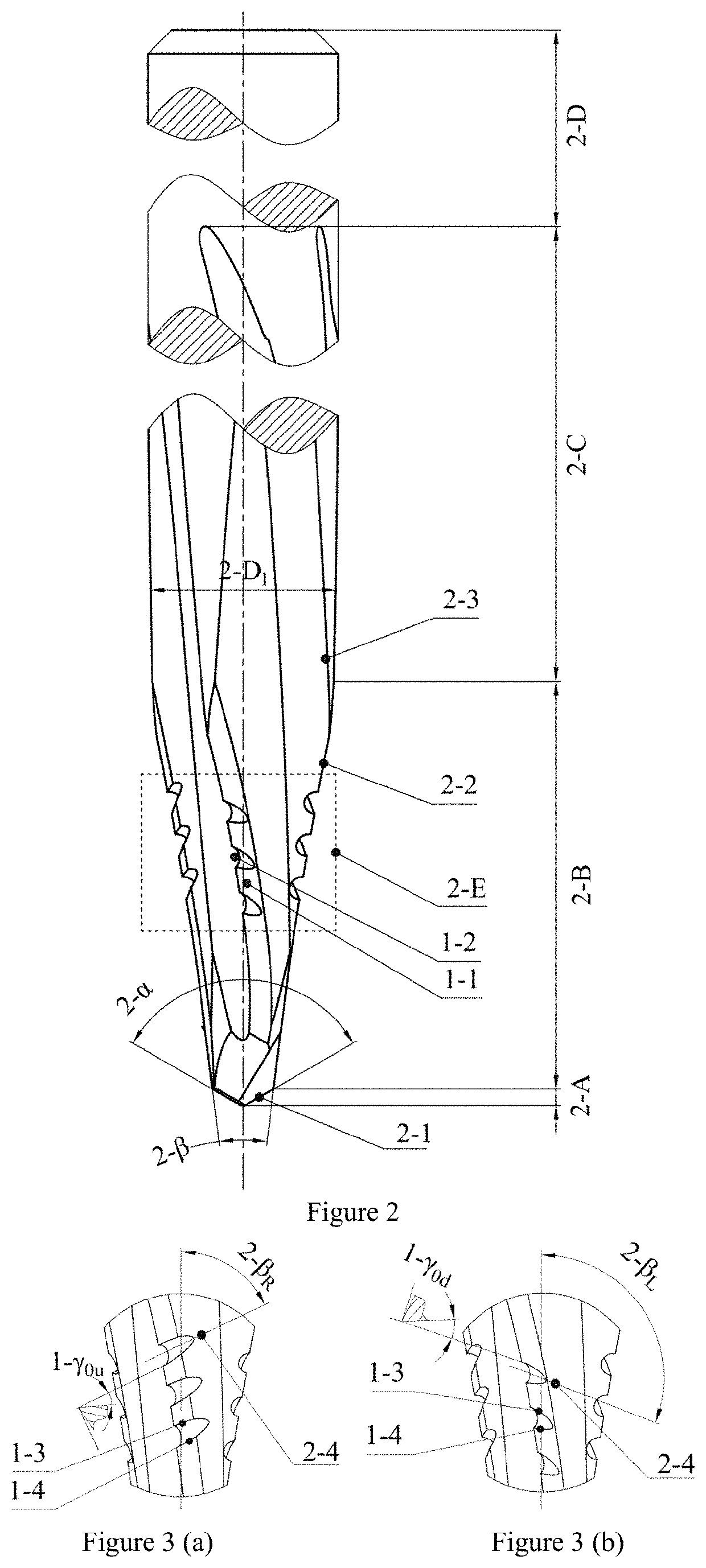
[0035]FIG. 2 shows an intersecting-sawtooth double point angle drill of claim 2. The drill can be divided into five zones: the primary cutting zone 2-A formed by the envelope curves of primary cutting edges 2-1, the secondary cutting zone 2-B formed by the envelope curves of secondary cutting edges 2-2, the left-hand minor cutting zone 2-C whose envelope curves are final hole, the clamping zone 2-D and the sawtooth cutting zone 2-E. Among them, the primary cutting zone 2-A has two primary cutting edges 2-1, and the first point angle 2-α is obtuse, which leads to the high rigidity of the primary cutting edge and preferable centering effect to ensure the drilling smoothly. The implementation adopts 2-α=118°; the secondary cutting zone 2-B has four secondary cutting edges 2-2, and the second point angle 2-β is acute, which results in the sharp secondary cutting edge 2-2, low thrust force and delamination. The minor cutting edge 2-3 adopts low left-hand helix angle to decrease thrust fo...

embodiment 2

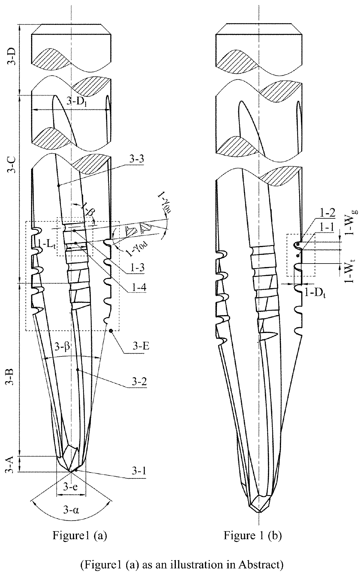
[0037]FIGS. 1(a) and (b) shows a right-hand-sawtooth double point angle drill of claim 3. The drill can be divided into four zones: the primary cutting zone 3-A, the secondary cutting zone 3-B, the minor cutting zone 3-C, and clamping zone 3-D. In addition, the sawtooth cutting zone 3-E locates in the joint of the secondary cutting zone 3-B and the minor cutting zone 3-C which consists of several sawteeth 1-1 and grooves 1-2. The sawtooth cutting zone 3-E is formed by the sawtooth structure distributed in each cutting edge. There are one sawtooth 1-1 in the secondary cutting edge and four sawteeth 1-1 in the minor cutting edge. The sawteeth 1-1 in all cutting edges is right-hand. The top edges 1-3 act as cutting edges and are ground into positive rake angle 1-γ0u that equals to 20°.

[0038]Drilling can be divided into five stages: The first stage is crushing. The chisel edge contacts and crushs the workpiece. Because of the crushing effect of it, thrust force increases rapidly; the se...

embodiment 3

[0041]FIGS. 4, 5 and 6 show a right-hand-sawtooth twist drill of claim 4. It can be divided into four zones: the primary cutting zone 4-A formed by the outline of the primary cutting edge 4-1, the minor cutting zone 4-B formed by the outline of the primary cutting edge 4-1 terminal and minor cutting edge 4-2, the clamping zone 4-C and the sawtooth cutting zone 4-D. Two primary cutting edges 4-1 develop low point angle 4-α, which is beneficial to decrease thrust force and delamination; the minor cutting edge 4-2 is designed with sawtooth structure, which realizes the rebounding into the sawtooth structure and cutting off for generating burrs in drilling. It can eliminate the burrs effectively at the exit and entrance, and decrease the cracks in the final hole; the minor cutting edge 4-2 adopts right-hand structure, and it contributes to removing burrs; each of the primary cutting edges 4-1 have two flank surfaces. It will decrease the friction between drill and workpiece, cutting hea...


PUM


Abstract

A kind of sawtooth structure with reversed cutting function and its drill series are presented in this invention. This invention is suitable for drilling low-damage holes on carbon fiber reinforced polymers (CFRP). The sawtooth structure is comprised of sawteeth and grooves located on the cutting edges of drill. And the sawtooth structure is helically arranged with a specific helix angle around the axis of the drill. It can be classified as the left-hand helix sawtooth structure and the right-hand helix sawtooth structure based on the helix angle value. The bottom edges of the left-hand helix sawtooth structure are the cutting edges, and the rake angles are positive; while the top edges of the right-hand helix sawtooth are the cutting edge with the positive rake angles. The sawtooth structure can be applied to various drilling tools, which proves to be universal. And it can effectively reduce delamination at both hole entrance and hole exit as well as burrs defects. The series of drilling tools include the double point angle drill, the twist drill and the stepped drill all of which have the sawtooth structure on the cutting edges. These series of drilling tools can achieve the CFRP holes with minimum drilling defects. The drilling performance of the tools is improved to a great extent, the tool life is extended and the costs are reduced.

Description

TECHNICAL FIELD[0001]The invention belongs to the drilling tool technical field in the mechanical machining, and relates to a sawtooth structure with reversed cutting function and its drill series. And the invention is specifically fitted for drilling carbon fiber reinforced polymer composites within one shot to guarantee high quality and high efficiency.BACKGROUND[0002]The fiber reinforced polymer (FRP) composites generally have excellent mechanical properties designable performance is and they are easy to be manufactured to the net shape. Therefore, the FRP composites are widely used in the manufacturing of structural parts in the aeronautical field and effectively reduce the weight of structural parts and the manufacturing cycle as well as improve reliability. It is especially true for carbon fiber reinforced polymer (CFRP) composites due to their high specific strength and specific stiffness, and the CFRP composites are usually applied for manufacturing the core load-bearing str...

Claims


Application Information

Patent Timeline
Patent Type & Authority Patents(United States)
IPC IPC(8): B23B51/02B23B51/08B23B51/00
CPCB23B51/08B23B51/02B23B51/009B23B2226/275B23B2251/285
Inventor JIA, ZHENYUANWANG, FUJIFU, RAOBAI, YUNIU, BINLIU, WEIMA, JIANWEIHE, CHUNLING
Owner BLUEDRILL TECH SHENZHEN CO LTD
Learn More