
Mobile device display and input expansion apparatus

a mobile device and display technology, applied in computing, portable computer details, instruments, etc., can solve the problems of limited inputs that can be provided to touch interfaces, limited extent of user interaction, and low power of mobile processors, so as to increase input capabilities, expand display output, and save costs

Active Publication Date: 2020-11-03
BT IDEA LABS LLC
View PDF8 Cites 0 Cited by
  • Summary
  • Abstract
  • Description
  • Claims
  • Application Information

AI Technical Summary

Benefits of technology

The present patent introduces an apparatus that allows users to replace their laptop or desktop computer with their smartphone as the main computing device. This means users don't need to use multiple components in a laptop or desktop computer, like the processor and video card, which are already in the smartphone. This offers cost savings and minimizes security concerns because the processing unit can be physically separated from the display and input method when not in use. Another advantage is that the single device (the smartphone) is already ubiquitous in the technology ecosystem, making it more convenient for users.

Problems solved by technology

Although differences between processors utilized in mobile devices and those utilized in desktop and notebook class personal computers are becoming less, earlier mobile processors were lower powered due to limited battery capacity, small form factors, and so on.
That is, the extent of any user interaction is limited to what can be displayed on the screen, and the inputs that can be provided to the touch interface are similarly limited to what can be detected by the touch input panel.
While the availability of productivity software applications for tablets, smartphones, and other mobile platforms are almost on par with those available for personal computers, the smaller form factor of the mobile devices tend to limit their use in such applications.

Method used


Image

  • Mobile device display and input expansion apparatus
  • Mobile device display and input expansion apparatus
  • Mobile device display and input expansion apparatus

Examples


second embodiment

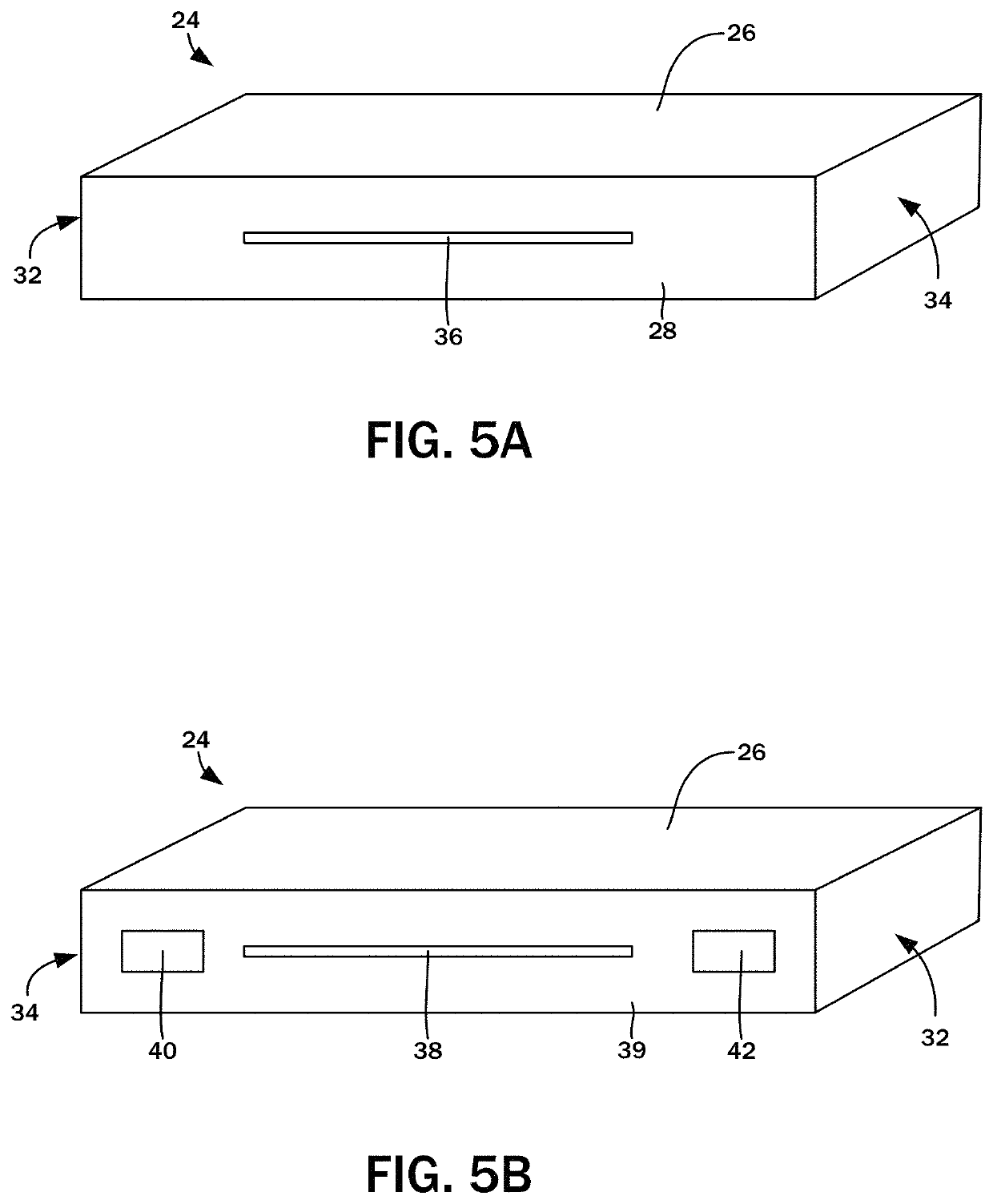
[0052]the bi-directional projection unit 24 similarly includes the laser diode projector 64 that generates the second series of light outputs corresponding to a virtual keyboard key arrangement 66. The light outputs of the virtual keyboard are projected against the front display surface 20b, also referred to as the keyboard projection surface of the second section 20 of the clamshell structure 16. The set of diffractive optic elements 68 are aligned with the output end of the laser diode projector 64 and the virtual keyboard projection aperture 38 defined in the second lengthwise edge wall 30 of the housing 26.

[0053]The second embodiment of the bi-directional projection unit 24b also incorporates the IR detector 70 and the CMOS imaging sensor 72 that determines key inputs that are captured by the input processor 74 and relayed to the mobile device 12 by the communications module 52. Again, it is understood that the break in the laser projection from the laser diode projector 64 is d...

third embodiment

[0058]the bi-directional projection unit 24 similarly includes the laser diode projector 64 that generates the second series of light outputs corresponding to a virtual keyboard key arrangement 66. The light outputs of the virtual keyboard are projected against the front display surface 20b, and specifically the keyboard projection surface of the second section 20 of the clamshell structure 16. The set of diffractive optic elements 68 are aligned with the output end of the laser diode projector 64 and the virtual keyboard projection aperture 38 defined in the second lengthwise edge wall 30 of the housing 26.

[0059]The third embodiment of the bi-directional projection unit 24c also incorporates the IR detector 70 that determines key inputs that are captured by the input processor 74 and relayed to the mobile device 12 by the communications module 52. The user inputs keystrokes by placing finger at a given one of the locations at which the corresponding virtual key is being projected. ...

fourth embodiment

[0067]the bi-directional projection unit 24d also incorporates the IR detector 70 and the CMOS imaging sensor 72 that determines key inputs that are captured by the input processor 74 and relayed to the mobile device 12 by the communications module 52. Again, it is understood that the break in the laser projection from the laser diode projector 64 is detected by the IR detector 70, and the CMOS imaging sensor 72 captures a sequence of images within its field of view that are processed to determine the haptic inputs upon the virtual keyboard key arrangement 66. The IR detector 70 is positioned within the housing 26 to be aligned with the second sensor aperture 42, while the CMOS imaging sensor 72 is positioned to be aligned with the first sensor aperture 40.

[0068]The pico projector 44 is mounted to a pair of thermal conductors or heat sinks 60a, 60b to transfer away the heat generated thereby. The laser diode projector 64 is mounted to a pair of thermal conductors or heat sinks 60c, ...


PUM


Abstract

An input / output expander for a mobile device has a communications module connectible thereto. Output display signals from the mobile device and input signals to the mobile device are relayed between the mobile device and the bi-directional projection unit by the communications module. A display output projector is connected to the communications module, and the output display signal from the mobile device is converted to a first series of light outputs corresponding to the output display signal. The expander has a virtual keyboard projector generating a second series of light outputs corresponding to a virtual keyboard key arrangement. A key input sensor with a sensing coverage area encompassing the virtual keyboard key arrangement detects user input at specific positions thereon. A key input value corresponding to a specific key of the virtual keyboard key arrangement is generated.

Description

CROSS-REFERENCE TO RELATED APPLICATIONS[0001]Not ApplicableSTATEMENT RE: FEDERALLY SPONSORED RESEARCH / DEVELOPMENT[0002]Not ApplicableBACKGROUND1. Technical Field[0003]The present disclosure relates generally to multi-purpose mobile computing devices, and more particularly, to an apparatus for expanding the input and display output capabilities of mobile devices.2. Related Art[0004]A variety of personal computing devices spanning a wide range of form factors are available, with each fulfilling specific needs and applications. Evolved from general-purpose desktop computers, notebook / laptop computers feature a clamshell form factor with a base portion incorporating the processor, memory, storage, and peripheral input / output ports. A keyboard and / or a trackpad or other like graphical user interface input modality may be disposed on the interior face of the base clamshell portion. The other half of the clamshell may be dedicated to the display. Such notebook computers are loaded with des...

Claims


Application Information

Patent Timeline
Patent Type & Authority Patents(United States)
IPC IPC(8): G06F3/0488G06F1/16
CPCG06F1/1643G06F1/1639G06F3/04886G06F1/1632G06F3/0426G06F1/1616G06F3/044
Inventor THIGPEN, KEVINBOLADIAN, JEAN-PIERRE
Owner BT IDEA LABS LLC
Learn More