
Process for steam drawing carbon-fiber precursor acrylic fiber bundle

a technology of carbon fiber and acrylic fiber, which is applied in the direction of liquid/gas/vapor textile treatment, liquid/gas/vapor yarn/filament treatment, other domestic articles, etc., can solve the problems of affecting the quality of carbon fiber fiber bundles. , to achieve the effect of preventing the breakage of a single filament or the fluff, preventing the breakage o

Active Publication Date: 2020-03-31
MITSUBISHI CHEM CORP
View PDF14 Cites 1 Cited by
  • Summary
  • Abstract
  • Description
  • Claims
  • Application Information

AI Technical Summary

Benefits of technology

[0013]According to the present invention, the efficient plasticizing effect can be obtained when the steam drawing process is performed on the acrylic fiber bundle, and a trouble involved with the breakage of the entire acrylic fiber bundle can be prevented even when the acrylic fiber bundle is drawn up to a high magnification, even when the process is performed at a high speed, and even when a fine fiber is to be obtained. Further, it is possible to prevent the breakage of a single filament or the fluff and hence to stably obtain a high-quality carbon-fiber precursor acrylic fiber bundle.

Problems solved by technology

However, when the acrylic fiber bundle is drawn up to a high magnification by the steam drawing process, problems in which single filaments are broken, fluffs occur, or the entire fiber bundle is broken may occur.

Method used


Image

  • Process for steam drawing carbon-fiber precursor acrylic fiber bundle
  • Process for steam drawing carbon-fiber precursor acrylic fiber bundle
  • Process for steam drawing carbon-fiber precursor acrylic fiber bundle

Examples


example 1

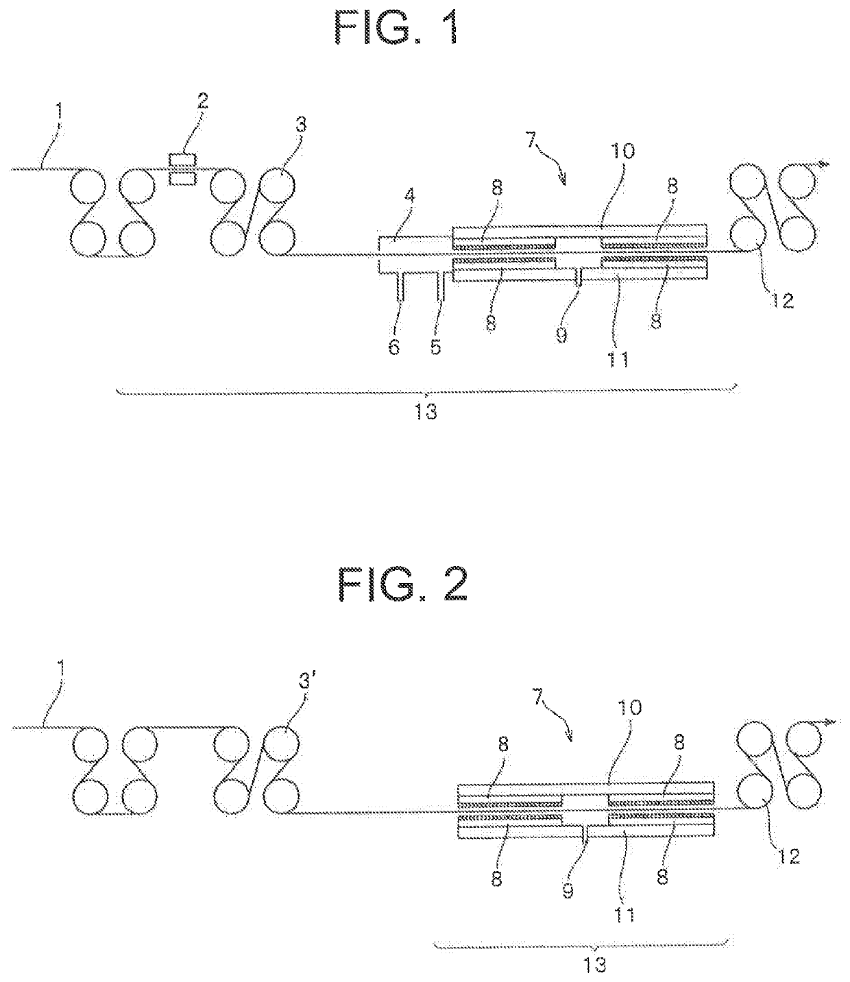
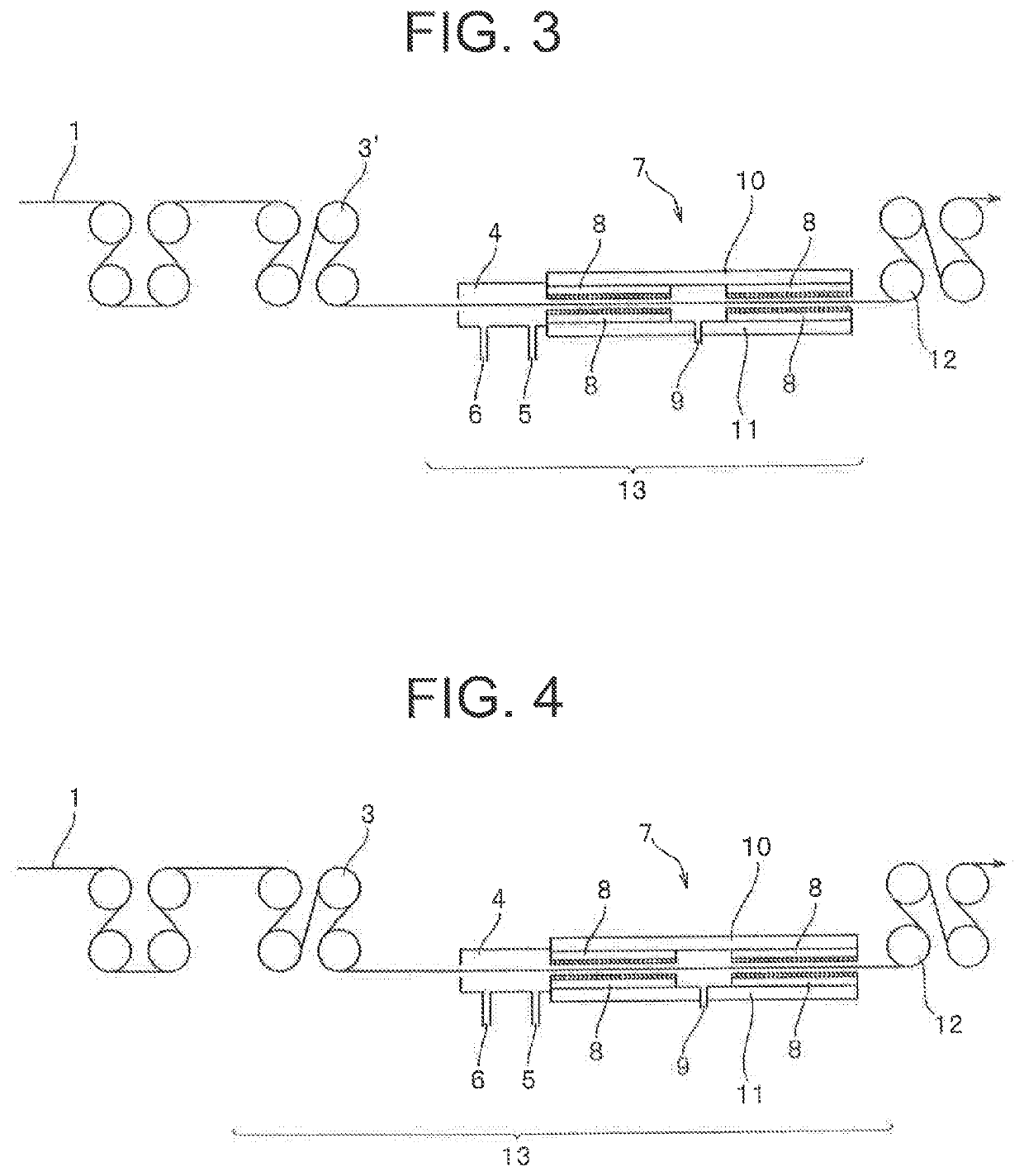
[0036]Acrylic copolymer including acrylonitrile of 98 mol % and methacrylic acid of 2 mol % was dissolved into dimethylformamide so as to prepare a spinning dope of a polymer concentration of 23%. The spinning dope was ejected from a spinning nozzle into a coagulating bath at a temperature of 10° C. and a concentration of 80% so as to obtain a coagulated yarn. The coagulated yarn was drawn in cold water and then drawn in hot water, and was subjected to an oil agent application and a dry densification process so as to obtain an acrylic fiber bundle. Subsequently, the acrylic fiber bundle was drawn 4.0 times using a steam drawing apparatus 13 shown in FIG. 1 so as to obtain a carbon-fiber precursor acrylic fiber bundle in which the single filament fineness was 1.0 decitex and the number of filaments was 12000.

[0037]In the steam drawing apparatus 13 shown in FIG. 1, the acrylic fiber bundle (the yarn) 1 is guided to the opening device 2 by a plurality of rolls. In the opening device 2,...

examples 2 to 5

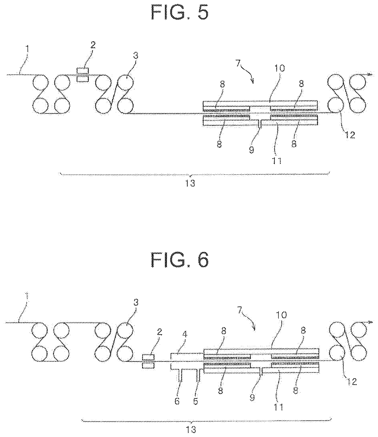
[0044]As shown in Table 1, the carbon-fiber precursor acrylic fiber bundle was obtained similarly to Example 1 except that the process condition of the steam drawing apparatus 13 was changed. A result for the evaluation of the number of times of breakage, the number of fluffs, and the breakage draw ratio of the obtained carbon-fiber precursor acrylic fiber bundle is shown in Table 1.


PUM

PropertyMeasurementUnit
pressureaaaaaaaaaa
flow rateaaaaaaaaaa
temperatureaaaaaaaaaa

Abstract

This process for manufacturing a carbon-fiber precursor acrylic fiber bundle and this steam drawing apparatus are characterized in that the drawing of an acrylic fiber bundle with a pressured-steam drawing apparatus is conducted by: opening an acrylic fiber bundle by blowing a fluid thereto; supplying humidifying steam to the opened acrylic fiber bundle at a fiber temperature of 80 to 130° C. to adjust the water content of the fiber bundle to 3 to 7%; and thereafter drawing the resulting acrylic fiber bundle in a pressurized-steam atmosphere. Thus, the present invention can prevent the breaking of a single fiber, the fluffing of the fiber bundle, and the breaking of the whole of the fiber bundle, though such defects are susceptible to occurring in a case where an acrylic fiber bundle is drawn by steam drawing at a high draw ratio, at a higher speed, or into a fiber having a small denier.

Description

TECHNICAL FIELD[0001]The present invention relates to a process for manufacturing a carbon-fiber precursor acrylic fiber bundle having a pressurized steam drawing step. Further, the invention relates to a pressurized steam drawing apparatus that draws an acrylic fiber bundle using pressurized steam.BACKGROUND ART[0002]As a method of drawing an acrylic fiber bundle, drawing in a pressurized steam atmosphere is known. This is because temperature higher than hot water in an atmospheric pressure can be obtained and moisture existing therein causes an effect of plasticizing the acrylic fiber bundle so that the fiber bundle can be drawn up to a high magnification. The carbon-fiber precursor acrylic fiber bundle used as a precursor of the carbon fiber particularly does not have a noticeable melting point due to the high acrylonitrile content, and the fiber bundle substantially cannot be drawn only by the effect of the high temperature. For this reason, the pressurized steam drawing process...

Claims


Application Information

Patent Timeline
Patent Type & Authority Patents(United States)
IPC IPC(8): D02J1/22D01D11/02D02J1/18D01F9/22D01F6/38B29C55/00D02J13/00D01F9/21D01F6/18D06B3/04D01D5/16D06C3/00B29K33/00B29L31/00
CPCD02J1/225D01F6/38D01F9/21D02J1/18D01F9/22D01D11/02D02J1/222D02J13/005B29C55/005D06C3/00D01D5/16D01F6/18B29L2031/731B29K2033/08D01F9/225D06B3/045
Inventor TADA, AKISHIGEMIZUTORI, YUKIHIRO
Owner MITSUBISHI CHEM CORP
Learn More