
Temperature detecting and controlling integration device and the temperature controlling method applied for micro speaker

a technology of temperature detection and control, applied in the direction of frequency response correction, volume compression/expansion having semiconductor devices, volume compression/expansion in untuned/low-frequency amplifiers, etc., can solve the problem of low correlation coefficient between temperature and voltage, distortion of the output waveform of the micro speaker s or permanent damage to the micro speaker s, etc. problem, to achieve the effect of smooth control and steady playback

Active Publication Date: 2020-01-07
SHANGHAI FOURSEMI SEMICON CO LTD
View PDF2 Cites 3 Cited by
  • Summary
  • Abstract
  • Description
  • Claims
  • Application Information

AI Technical Summary

Benefits of technology

The present invention is related to a micro speaker with a temperature detection and control function. The device can detect the temperature of the micro speaker's coil to prevent reduced sound quality. Additionally, it can control the power amplification of the micro speaker within a safe range to protect it from damage. The invention provides a method for accurately detecting the coil temperature and adjusting the power amplifier's amplification ratio accordingly. This allows for smooth control of the micro speaker's temperature and ensures consistent playback of sound signals.

Problems solved by technology

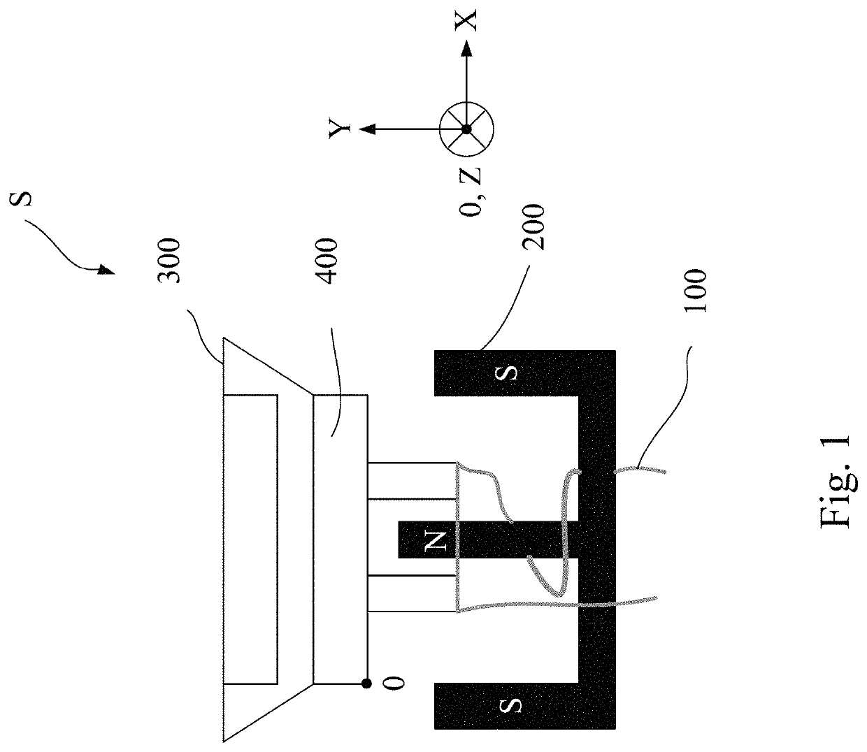
Based on the aforementioned, the distortion of the output waveform of the micro speaker S is to be generated or the micro speaker S is permanently to be damaged.
At the same time, the overheating of the coil 100 can also result in permanent damage of the magnet 200.
Although the previous method can only obtain the temperature from the voltage conversion, but the correlation coefficient between the temperature and the voltage is low, and the coefficient of variation is large.
Thus, by using the voltage conversion to obtain the temperature is inaccurate.
Therefore, above technology cannot satisfy the requirements of the users for the music appreciation on the sound quality.
Moreover, the prior art did not disclose how the actual voltage is converted into the temperature clearly, so that the authenticity of the temperature value cannot be judged.
Although the prior art utilizes the resistance to obtain the voice coil temperature to increase the realism of the temperature, but the instantaneous temperature measured by the sensor still contains noise, the noise still cause that the coil temperature is inaccurate.
In addition, because the temperature is a long-term variation process, if the temperature is obtained based on the instantaneous physical quantity, the obtained temperature may be inaccurately.
Moreover, each measurement resistance will inevitably lead to current loss, so the sound quality of the micro speaker still would be reduced.
In addition, when the micro speaker S is in operation, the conversion efficiency of the electric energy is transduced into acoustic energy is not achieved 100%, so that the heat dissipation would be generated by the coil of the micro speaker S. The heat dissipation will also have conducted to the neighboring driving circuit to cause the internal temperature of the driving circuit of the micro speaker S is increased.
Although the driving circuit has already considered the influence of the heat dissipation on it operation stability at the beginning of the design, however, a long-term high operating temperature inevitably introduces to a decrease in the operating life of the driving circuit, and the instantaneous elevated temperature may cause the damage.
For example, if the power amplification at the power amplifier in the micro speaker is 12 dB at a certain time, the sound of the micro speaker S is malfunctioned instantaneously, but it will cause the permanent damage to the micro speaker.

Method used

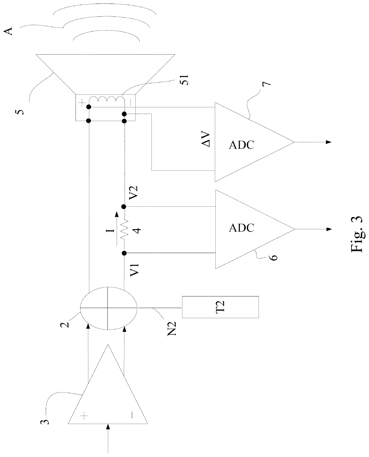

Image

  • Temperature detecting and controlling integration device and the temperature controlling method applied for micro speaker
  • Temperature detecting and controlling integration device and the temperature controlling method applied for micro speaker
  • Temperature detecting and controlling integration device and the temperature controlling method applied for micro speaker

Examples


Embodiment Construction

[0036]Some sample embodiments of the invention will now be described in greater detail. Nevertheless, it should be recognized that the present invention can be practiced in a wide range of other embodiments besides those explicitly described, and the scope of the present invention is expressly not limited except as specified in the accompanying claims.

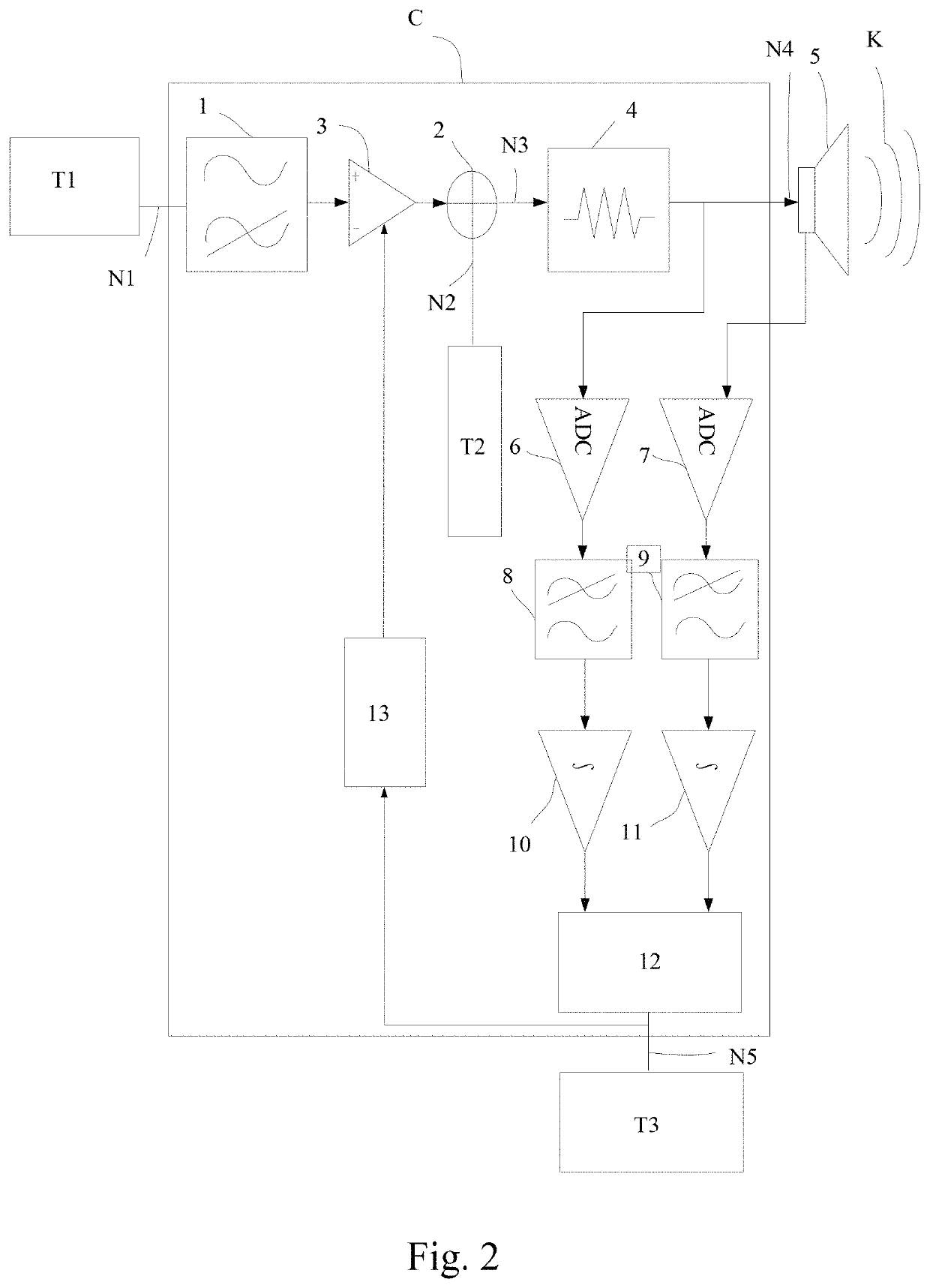
[0037]Please refer to FIG. 2. FIG. 2 shows a circuit block diagram of a temperature detecting and controlling integration device. As shown in FIG. 2, the temperature detecting and controlling integration device C is coupled with a computer T1, a micro speaker 5 and an external device T3 respectively. The temperature detecting and controlling integration device C can be a chip with six pins (not shown in FIG. 2), one of six pins of the chip is coupled to the computer T1, a four of six pins of the chip is coupled to the micro speaker 5, or other one of the six chip is coupled to the external device T3. The temperature detecting and contr...


PUM


Abstract

A temperature detecting and controlling integration device for the micro speaker is provided. After the filter receives an input signal, the power amplifier adjusts the power amplification, and the multi-frequency detection signal is generated with the waveform generator. The extracted signal is generated to drive the micro speaker to emit a sound signal. Afterwards, the voltage signals are extracted at two ends of the coil and the temperature signal is obtained by converting, capturing, and integrating to pass the temperature value to the external device, and the temperature value of the non-linear temperature-controlling unit is analyzed to adjust the compensation gain in real time. The smoothly control of speaker temperature and stable playback of the sound signals is played that can be achieved.

Description

CROSS-REFERENCE TO RELATED APPLICATIONS[0001]This application claims priority to China Patent Application No. 201711059595.8, filed on Nov. 1, 2017, China Patent Application No.[0002]201711080667.7, filed on Nov. 6, 2017, and China Patent Application No. 201810492803.1, filed on May 22, 2018, the content of which are hereby incorporated by reference in their entirety.FIELD OF THE INVENTION[0003]The present invention related to a temperature detecting and controlling integration device for a micro speaker, and more particularly to a temperature controlling method by using an integrated circuit to detect the temperature and adjust the compensation gain for the micro speaker.DESCRIPTION OF THE PRIOR ART[0004]The micro speaker is usually a speaker that is set in a portable device and the volume is within 15 mm*15 mm in size, and has an output power of less than 2 watts. The micro speaker can applied for the electronic products, such as mobile phone, notebook, or personal digital assista...

Claims


Application Information

Patent Timeline
Patent Type & Authority Patents(United States)
IPC IPC(8): H04R3/00H03F3/24H03F3/183H03G3/30H04R3/04H04R29/00
CPCH03F3/183H04R3/04H03G3/3005H04R29/001H03F3/245H04R3/007H03F2200/165H03G2201/103H03F2200/03H03G7/002H03G7/08H04R29/003
Inventor DING, XUEXINLIU, WEIJIXU, JIANZHANG, LINLIU, XIAOLEIJIANG, YINGSHUNSHEN, FANGKANG
Owner SHANGHAI FOURSEMI SEMICON CO LTD
Learn More