Dynamic focus and zoom system for use with wide-field, confocal and multiphoton microscopes

a multi-photon microscope and dynamic focus technology, applied in the field of microscope technology, can solve the problems of damage to samples, unliving, fixed samples, thin samples,

Active Publication Date: 2019-11-05
AGILE FOCUS DESIGNS LLC
View PDF14 Cites 2 Cited by
  • Summary
  • Abstract
  • Description
  • Claims
  • Application Information

AI Technical Summary

Problems solved by technology

For this reason, most samples are thin, un-living, and fixed.
Disadvantages of traditional focusing mechanisms include agitation of the sample with translation of the stage (which can result in difficulty finding focus when observing solid particulates in liquids, damage to samples when they accidentally hit the objective lens, slow focus control (typically less than 100 Hz speed even with automated stages), inaccurate focusing, excessive photodamage from overexposure, early termination of experiments due to reaction completion prior to observation (due to the excessive time it takes to find a focal plane of interest), and the inability to observe biological phenomenon at small timescales due to speed-of-imaging limitations, such as observation of neurons propagating in real-time in living samples.
Automated sample stages are limited to discrete focus step locations and traditional zoom systems to discrete magnification changes.
Resonant objective lens scanners do not maintain optical resolution over the focusing range, operate only at a single (relatively fast) speed, and have a moving mass, which causes them to vibrate or shake the system as they resonate.
Although varifocus lenses (including MEMS mirrors) have been used in connection with some confocal and multiphoton microscopes to achieve greater focus, they have not been used for optical zoom in microscopy, nor have they been incorporated into a small and portable unit that is user-friendly for the common biologist.
Commercial varifocus lenses are difficult to use for the average biologist; for example, most dynamic focusing mechanisms that are situated at the beginning of the optical train in a microscope require installation by an engineer.
These are usually custom jobs with a single varifocus element done at elite universities for one experiment only, thereby precluding widespread use.
Liquid lenses, which are another form of varifocus lens, do not maintain optical resolution over the focusing range, are not achromatic, and cannot effectively control attendant spherical aberration.
The preceding paragraph addresses some of the challenges that exist with current varifocus lens technologies; as stated above, there is no existing technology that utilizes varifocus lenses to achieve optical zoom in microscopy.
It is difficult to switch from low magnification of a large area to high magnification of a small area while concurrently manipulating a sample with one's hands.
There is currently no solution for fast optical focusing or zoom that is easily used with (or attached to) a microscope.
One drawback of Theriault's single lens is that it requires a pulsed laser or camera and an iris for focusing, none of which is necessary in the present invention.
Specifically, the 2014 paper did not address the use of three MEMS mirrors, aligned as described herein, to accomplish independent adjustment of focusing and zoom.

Method used


Image

  • Dynamic focus and zoom system for use with wide-field, confocal and multiphoton microscopes
  • Dynamic focus and zoom system for use with wide-field, confocal and multiphoton microscopes
  • Dynamic focus and zoom system for use with wide-field, confocal and multiphoton microscopes

Examples


first embodiment

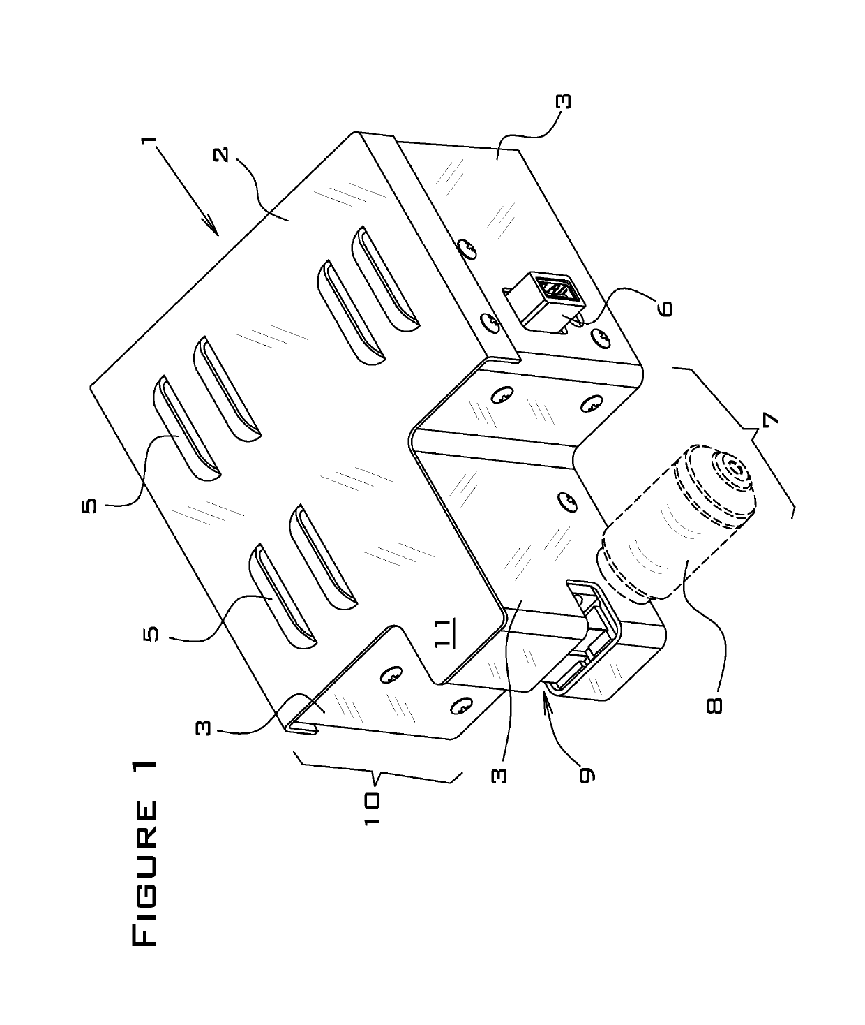
[0106]FIG. 1 is a first perspective view of the present invention. As shown in this figure, the present invention is comprised of a housing that forms an enclosure around the other components of the invention. The housing has a top cover 2, side walls 3 and floor (not shown). The top cover 2 may be attached, secured or connected to or joined with the side walls 3 in any manner; although shown here as attached to the side walls 3 with screws, the present invention is not limited to this particular manner of attaching the top cover 2 to the side walls 3. In an alternate embodiment, the top cover 2 and side walls 3 may be integrally molded (part of the same part) or welded together. The housing 1 may be made of any suitable, durable and rigid material (such as aluminum). In a preferred embodiment, the top cover 2 is comprised of one or more air vents 5 for heat dissipation.

[0107]FIG. 1 also shows the first USB 6. In this invention, there is one USB for each of the three MEMS mirrors (n...

second embodiment

[0120]FIG. 8 is a first perspective view of the present invention in which the objective lens is attached directly to the housing, and FIG. 9 is a second perspective view of the embodiment shown in FIG. 8 in which the objective lens turret is attached directly to the housing. In this particular embodiment, the device can be attached directly to an existing microscope. As shown, the objective lens 8 screws into the housing at position “Y” (see FIG. 6 for position designations) via a first threaded adapter 34 that is integral to the housing 1. The objective lens turret (not shown) screws into the housing at position via a second threaded adapter 35 that is also integral to the housing 1. The main window 9 has been eliminated (because the objective lens and objective lens turret are screwed directly into the housing), and the extension 11 has been lengthened to accommodate the threaded adapters 34, 35, but in all other respects, the invention is as previously described.

[0121]The follow...

third embodiment

[0133]FIG. 13 is a bottom perspective view of the present invention. As shown in this figure, the apparatus may be secured to an optical bench with screws 44. The objective lens turret (not shown) is attached to a second side wall 38 of the housing 36 via a second threaded adapter 45 that is preferably integral to the housing 36. This attachment point is referred to herein as the second portal 59. The slot 46, discussed further in connection with FIG. 16, is also shown.

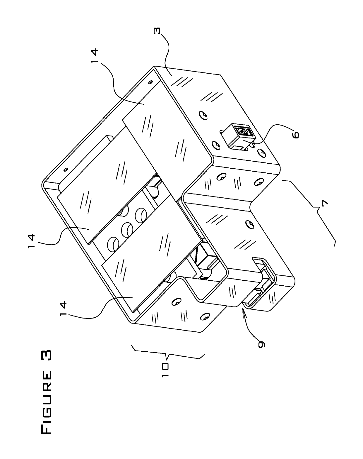
[0134]FIG. 14 is the same view as that shown in FIG. 12 except with the top cover of the housing removed. As shown in this figure, the USB 41 is connected to a printed circuit board 48 within the housing 36. In a preferred embodiment, the printed circuit board 48 controls all three MEMS mirrors 51, 52, 56. The objective lens 42 and threaded adapters 43, 45 are omitted from subsequent figures for clarity. Note that various threaded adapters may be used to connect either the objective lens 42 or the objective lens turre...


PUM


Abstract

A dynamic focus and zoom system for use with wide-field, confocal and multiphoton microscopes having first, second and third MEMS mirrors situated within a housing. First and second fixed lenses form an optical relay. A prism / mirror is situated proximate to a first portal in the housing and is aligned linearly with the optical relay and a first MEMS mirror. The second MEMS mirror is proximate to and at a ninety-degree angle relative to the first MEMS mirror, which is at a forty-five-degree angle to the second fixed lens. The second MEMS mirror, third fixed lens and third MEMS mirror are aligned linearly, with the third fixed lens situated between the second and third MEMS mirrors. The third MEMS mirror is proximate to a second portal in the housing. The third MEMS mirror is situated adjacent to the prism / mirror.

Description

CROSS-REFERENCE TO RELATED APPLICATION[0001]The present application is a continuation-in-part of U.S. patent application Ser. No. 15 / 706,331 filed on Sep. 15, 2017, the contents of which are incorporated herein by reference.STATEMENT REGARDING FEDERALLY SPONSORED RESEARCH OR DEVELOPMENT[0002]This invention was made with government support under Contract No. 1548737 awarded by the National Science Foundation on Jan. 1, 2016. The government has certain rights in the invention.BACKGROUND OF THE INVENTION1. Field of the Invention[0003]The present invention relates generally to the field of microscope technology and, more specifically, to a dynamic focus and zoom system for use with wide-field, confocal and multiphoton microscopes.2. Description of the Related Art[0004]People who work with microscopes on a daily basis generally assume that they consist of a few translatable or rotational (rotating in / out) fixed local length lenses or that different objective lenses need to be used to ach...

Claims


Application Information

Patent Timeline
Patent Type & Authority Patents(United States)
IPC IPC(8): G02B26/08G02B5/04G02B21/02G02B15/14G02B21/00G02B21/24
CPCG02B15/14G02B26/085G02B21/025G02B5/04G02B21/241G02B21/006G02B26/0825G02B5/08
Inventor LUKES, SARAH
Owner AGILE FOCUS DESIGNS LLC
Why Eureka
Try Eureka