
Res-Q-Scope

a glottis and esophagus technology, applied in the field of instruments, can solve the problems of wasting patient time, affecting the safety of patients, so as to minimize the effort of both patients, the effect of convenient use and efficien

Inactive Publication Date: 2005-04-28
CUBB ANTHONY
View PDF4 Cites 149 Cited by
  • Summary
  • Abstract
  • Description
  • Claims
  • Application Information

AI Technical Summary

Benefits of technology

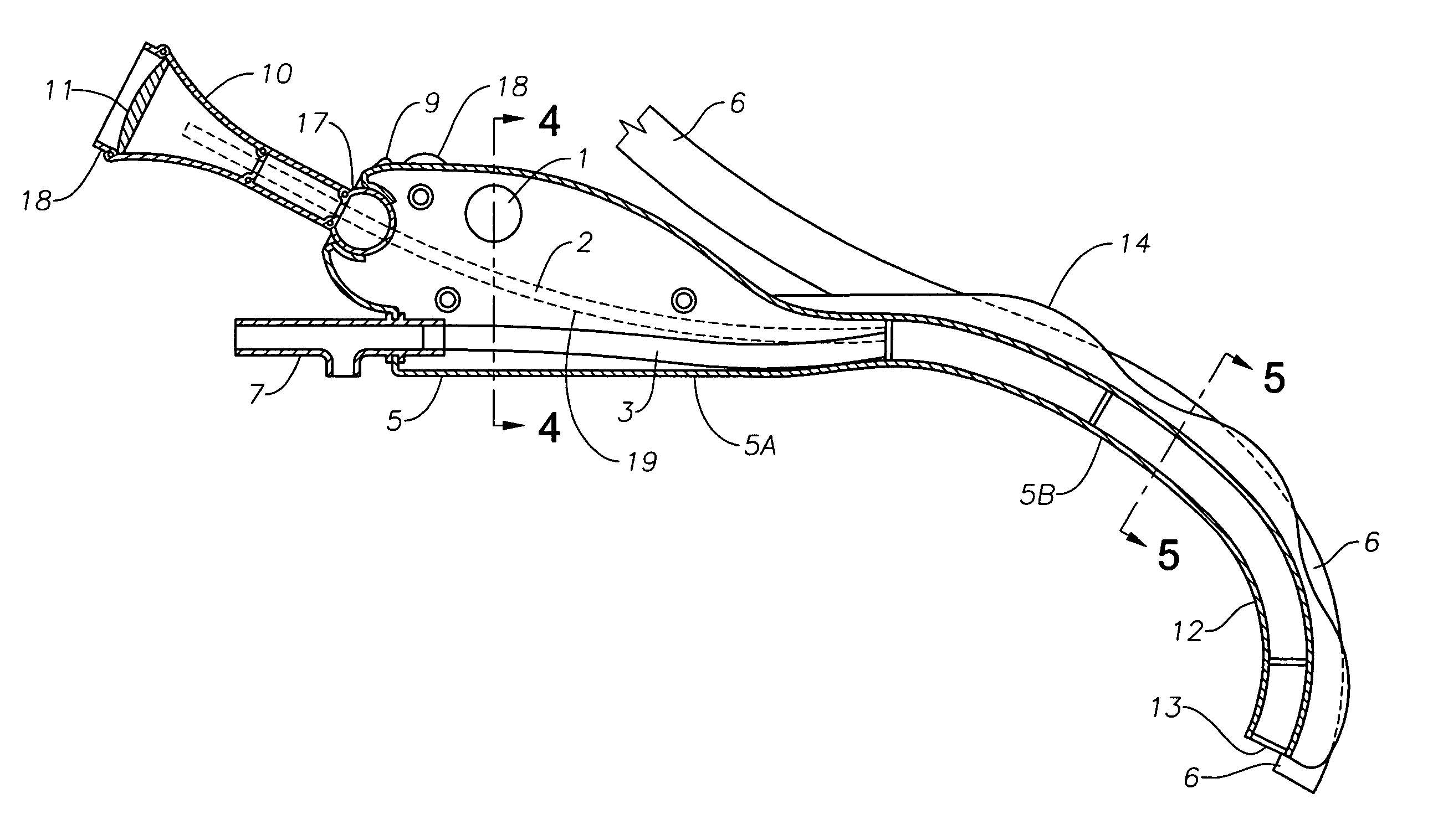
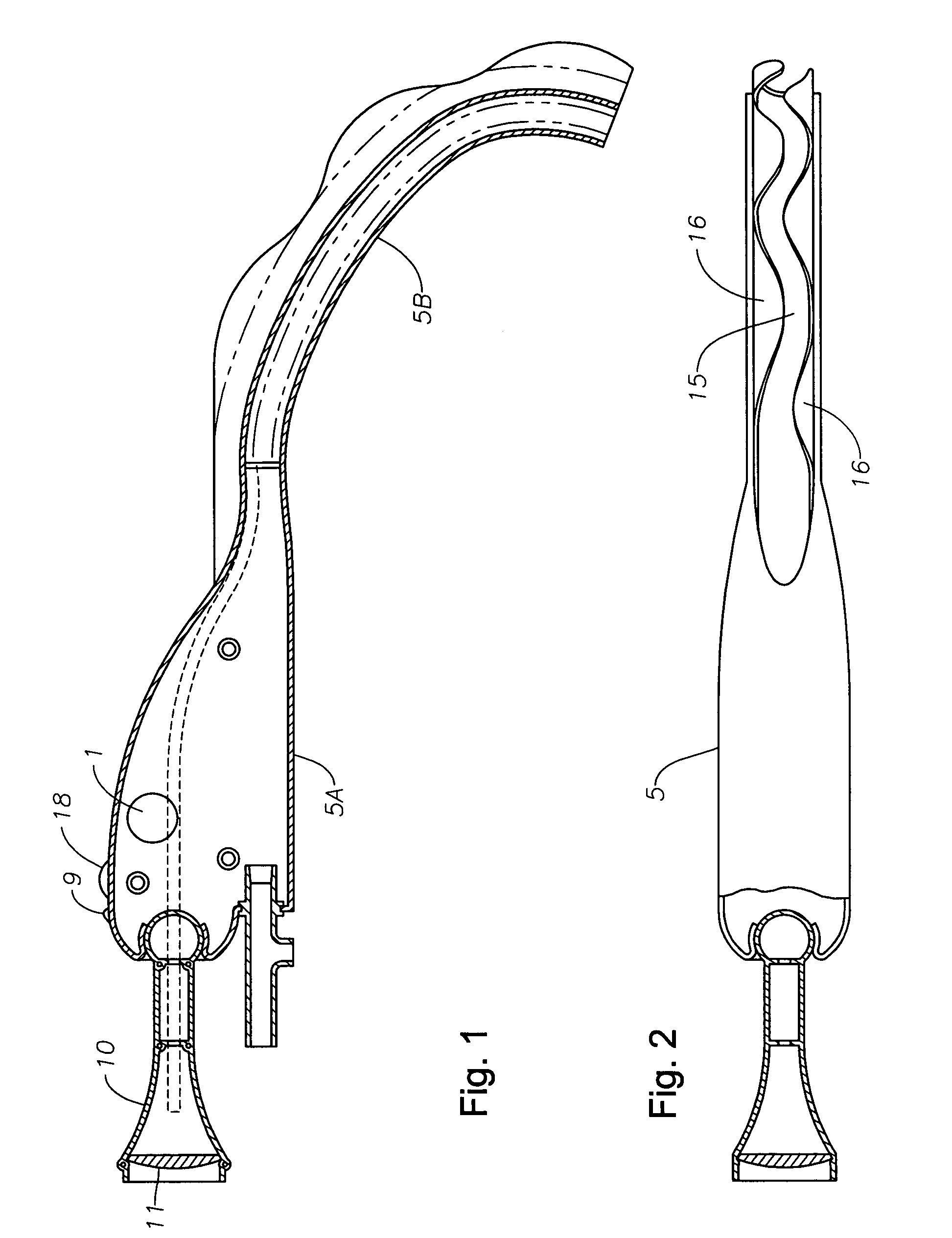
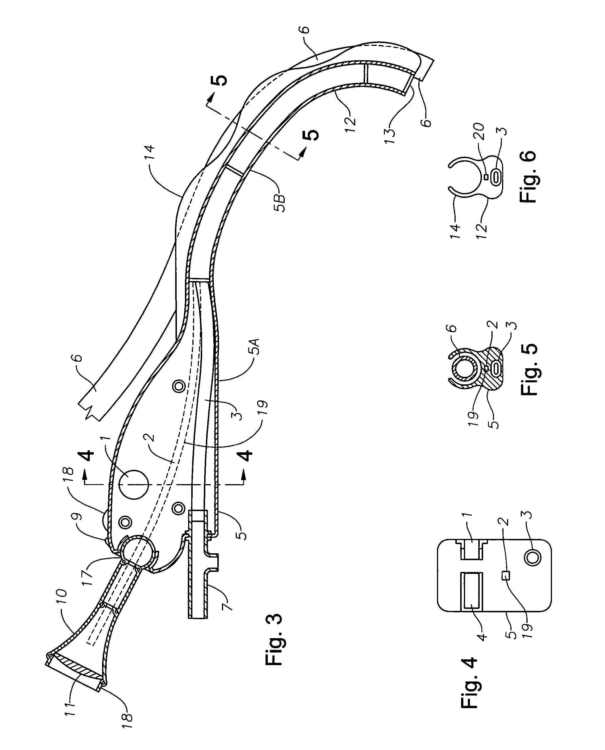
[0007] The present invention is designed to overcome the aforementioned difficulties during intubation by providing a disposable, inexpensive, easily used and efficient endotracheal intubation device, designed for ready manipulation of oral cavity soft tissue during placement to minimize the effort of both patient and operator, containing a bright light source and indirect visualization system composed of either fiberoptic bundles, a digital imaging system or a combination thereof, simultaneous suctioning ability, and external viewing mechanism which can be placed at a multiplicity of positions relative to the patient or allow for a multiplicity of locations of the operator relative to the patient that enables an operator to visualize the anatomical structure in front of the end point of the intubation device insertion from any orientation of the practitioner relative to the patient during insertion of the device and / or endotracheal tube of varying size.
[0008] In one preferred embodiment, an endotracheal intubation device is provided including an optical assembly enclosed by a housing anatomically accommodating to the operator's hand where the optical assembly includes an image conducting system having a curved distal portion and extending from a first end of the housing, and a proximal portion and extending from a second end of the housing through an image viewing mechanism pivotally attached at a first end of the viewing mechanism to the second end of the housing. The image viewing mechanism has at its second end a viewing system wherein the image conducting system optically communicates with the viewing system through the image viewing mechanism. The ball joint of the image viewing mechanism can be manipulated by application of light force applied to the image viewing mechanism such that a plurality of angular orientations with respect to the housing are achieved. Positioned at the second end of the image viewing mechanism is a viewing system which optically communicates with the image conducting system. The viewing system provides for accurate viewing by the practitioner when the practitioner's eye is within a comfortable field of vision of the operator from the viewing port.

Problems solved by technology

Additionally, if there is concern that the patient may have suffered spinal injuries, the technique for possible direct visualization of the glottis involves risk due to the potential for increased spinal injury from this procedure.
Without visualization of anatomical structure, intubation of a patient during an emergency situation may require blind placement of an endotracheal tube based on free hand trial and error.
Without proper positioning and guidance, the tubular members often cause trauma or injury to anatomical tissue, or missed intubation into the esophagus with potential fatal consequences.
Such devices obviously require the use of relatively large diameter endotracheal tubes in order to be carried on the tubular probe, and their use necessarily is limited to patients with sufficiently large airway passages to accommodate the combined size of the probe and endotracheal tube.
Additionally, due to the flexible nature of the probes, it is difficult to manipulate the probe to displace the tongue and epiglottis to permit guidance during insertion of the tube into the trachea.
These instruments require a high degree of skill and a concomitant degree of training to perform the procedure quickly, without injuring the patient.
Additionally, because of expense, lack of portability, and sterilization requirements to prevent cross contamination among patients, these instruments are generally not available in a non-hospital setting.

Method used


Image

  • Res-Q-Scope
  • Res-Q-Scope
  • Res-Q-Scope

Examples


Embodiment Construction

[0018] This description of preferred embodiments is intended to be read in connection with the accompanying drawings, which are to be considered part of the entire written description of this invention. The drawing figures are not necessarily to scale and certain features of the invention may be exaggerated in scale or in somewhat schematic form in the interest of clarity and conciseness. In the description, relative terms such as “horizontal,”“vertical,”“up,”“down,”“top” and “bottom” as well as derivatives thereof (e.g., “horizontally,”“downwardly,”“upwardly,” etc.) should be construed to refer to the orientation as then described or as shown in the drawing figure under discussion. These relative terms are for convenience of description and normally are not intended to require a particular orientation. Terms including “inwardly” versus “outwardly,”“longitudinal” versus “lateral” and the like are to be interpreted relative to one another or relative to an axis of elongation, or an a...


PUM


Abstract

A multiple function laryngoscope to be used for the safe intubation of a patient's trachea during a respiratory emergency or as an elective procedure. A two section instrument. Proximally, a reusable handle that houses a rechargeable battery, electronic circuits that feed a distal digital image to variable position LCD screen or viewing port, switches and low battery indicator light. Distally, the handle electrically couples with a disposable curved scabbard. The scabbard features a dorsal endotracheal tube channel with a wavy opening which allows preloading and gentle extraction of different size endotracheal tubes once the patient's trachea has been intubated. The scabbard's distal end strategically houses a distal sweeper that engages the epiglottis and exposes the glottis, an opening for the exit of a preloaded endotracheal tube, a LED light, a suction / oxygenation port, and a lens coupled with a digital imaging system (CMOS) to digitize and transport a distant wide field of view. Safe LCD view of one or serial rapid intubations are possible by rapidly replacing for a clean disposable scabbard in case of multiple emergencies.

Description

FIELD OF THE INVENTION [0001] The present invention generally relates to an instrument for accessing the laryngeal area of the human body and, more particularly, to an improved laryngoscope to use in the respiratory emergency field and hospital setting for safe, indirect, visual endotracheal intubation. BACKGROUND OF THE INVENTION [0002] Laryngoscopes are widely known and used in the medical field to facilitate endotracheal intubation of a patient during a respiratory emergency situation in order to provide airway patency and positive air pressure through the upper airway and the lungs, manually or through mechanical ventilation of the lungs to the injured person. Such laryngoscopes are also used during surgical procedures to maintain an open airway and provide ventilatory support during surgery under anesthesia. In the human anatomy, the epiglottis normally overlies the glottis opening into the larynx to prevent the passage of food into the trachea during eating. Thus, when underta...

Claims


Application Information

Patent Timeline
IPC IPC(8): A61B1/07A61B1/12A61B1/267A61M16/04
CPCA61B1/00073A61B1/00094A61B1/00195A61M16/0488A61B1/267A61M16/0825
Inventor CUBB, ANTHONY
Owner CUBB ANTHONY
Learn More