Using three or more masks to define contact-line-blocking components in FinFET SRAM fabrication

a technology of contact line blockage and finfet sram, which is applied in the direction of semiconductor devices, electrical apparatus, transistors, etc., can solve the problems of undesirable snm reduction caused by increasingly smaller transistor geometries, adversely affecting finfet sram performance and/or reliability, and undesirable bridging

Active Publication Date: 2019-10-22
TAIWAN SEMICON MFG CO LTD
View PDF32 Cites 0 Cited by
  • Summary
  • Abstract
  • Description
  • Claims
  • Application Information

AI Technical Summary

Benefits of technology

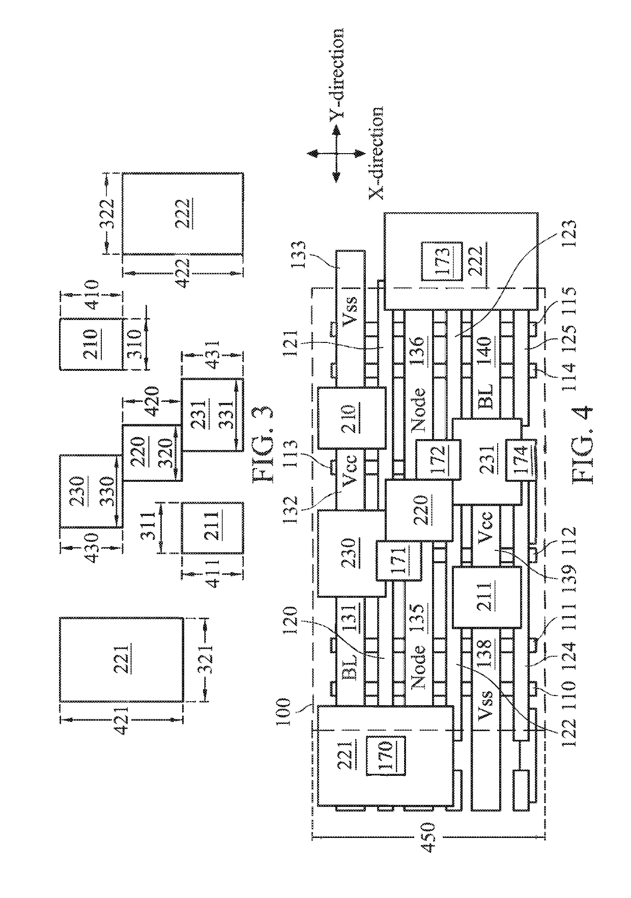
[0110]Based on the above discussions, it can be seen that the present disclosure offers advantages over conventional fabrication of FinFET SRAM devices. It is understood, however, that other embodiments may offer additional advantages, and not all advantages are necessarily disclosed herein, and that no particular advantage is required for all embodiments. One advantage is that the present disclosure reduces the contact bridging risks. By splitting the contact-line-blocking mask patterns onto three or more lithography masks, there is now a greater degree of freedom in tuning the mask patterns on each lithography mask. For example, some patterns may be stretched or enlarged in a predefined direction so as to maximize the likelihood of breaking up the SRAM contacts in a subsequent fabrication process. Another advantage is that the three or more lithography masks may each have improved pattern uniformity, as the mask patterns may each be shaped as a rectangle and / or may have similar dimensions to one another. The improved pattern uniformity in turns leads to improved lithography performance. Other advantages include compatibility with existing FinFET SRAM design and manufacture, so implementation of the present disclosure is easy and cheap.

Problems solved by technology

This reduction in SNM caused by increasingly smaller transistor geometries is undesirable.
In addition, as FinFET SRAM cell sizes shrink, undesirable bridging may occur.
These problems could adversely impact FinFET SRAM performance and / or reliability.
Therefore, although existing FinFET SRAM devices have been generally adequate for their intended purposes, they have not been entirely satisfactory in every aspect.

Method used


Image

  • Using three or more masks to define contact-line-blocking components in FinFET SRAM fabrication
  • Using three or more masks to define contact-line-blocking components in FinFET SRAM fabrication
  • Using three or more masks to define contact-line-blocking components in FinFET SRAM fabrication

Examples


Embodiment Construction

[0015]The following disclosure provides many different embodiments, or examples, for implementing different features of the provided subject matter. Specific examples of components and arrangements are described below to simplify the present disclosure. These are, of course, merely examples and are not intended to be limiting. For example, the formation of a first feature over or on a second feature in the description that follows may include embodiments in which the first and second features are formed in direct contact, and may also include embodiments in which additional features may be formed between the first and second features, such that the first and second features may not be in direct contact. In addition, the present disclosure may repeat reference numerals and / or letters in the various examples. This repetition is for the purpose of simplicity and clarity and does not in itself dictate a relationship between the various embodiments and / or configurations discussed.

[0016]F...


PUM


Abstract

A plurality of gate stacks is formed over a substrate. The gate stacks are surrounded by a dielectric structure. A plurality of contact-line-blocking patterns is formed over the dielectric structure. The contact-line-blocking patterns are formed using three or more lithography masks. A plurality of trenches is formed in the dielectric structure. The contact-line-blocking patterns serve as protective masks for the dielectric structure to prevent trenches from being formed in portions of the dielectric structure underneath the contact-line-blocking patterns. The trenches are filled with a conductive material to form a plurality of contact lines of the SRAM device.

Description

PRIORITY DATA[0001]This application is a divisional of U.S. application Ser. No. 15 / 691,868, filed Aug. 31, 2017, the disclosure of which is incorporated herein in its entirety.BACKGROUND[0002]In deep sub-micron integrated circuit technology, an embedded static random access memory (SRAM) device has become a popular storage unit of high speed communication, image processing and system-on-chip (SOC) products. The amount of embedded SRAM in microprocessors and SOCs increases to meet the performance requirement in each new technology generation. As silicon technology continues to scale from one generation to the next, the impact of intrinsic threshold voltage (Vt) variations in minimum geometry size bulk planar transistors reduces the complimentary metal-oxide-semiconductor (CMOS) SRAM cell static noise margin (SNM). This reduction in SNM caused by increasingly smaller transistor geometries is undesirable. SNM is further reduced when Vcc is scaled to a lower voltage.[0003]To solve SRAM...

Claims


Application Information

Patent Timeline
Patent Type & Authority Patents(United States)
IPC IPC(8): H01L27/11H01L21/311H01L21/768H01L21/8238H01L27/092H01L21/265H01L21/02H01L29/78
CPCH01L27/1104H01L21/26513H01L21/31144H01L21/823821H01L21/823828H01L27/0924H01L21/76877H01L21/823871H01L29/785H01L21/02532H01L21/76802H10B10/12H01L21/76897H01L21/76816H01L21/0337H01L21/0273H10B10/00
Inventor HUANG, SHIH-HANHSIEH, CHIH-HUNG
Owner TAIWAN SEMICON MFG CO LTD
Why Eureka
Try Eureka