Directly driven driving axle having two drive motors

Active Publication Date: 2006-09-26
HARLAN GLOBAL MFG
View PDF10 Cites 35 Cited by
  • Summary
  • Abstract
  • Description
  • Claims
  • Application Information

AI Technical Summary

Benefits of technology

[0005]The basic concept of the invention is that disposed on the axle are two separately operating asynchronous motors, the operating performance of which is controlled by a common control means, and the motor shafts of the two asynchronous motors are respectively connected, via the planetary gearing stage, with the drive shaft that drives the following output shaft. The invention has the advantage that due to the elimination of the differential, the operating noises resulting therewith are reduced, whereby a simplification and standardization of the structural form and the required individual components for the drive axle are also provided. Even if one of the separately driven wheels loses traction, the vehicle equipped with the drive axle continues to move with half power, because the wheel that continues to have traction is furthermore directly driven by the drive motor associated with it. Due to the direct coupling of the planetary gearing stage, which is provided between the drive shaft and the motor shaft, with the motor shaft on the one hand and the drive shaft on the other hand, there results a large degree of freedom in the structural design of the ratio of this gearing stage; a greater output torque or a higher final speed can be achieved therewith. There is also the further advantage that while maintaining the output torque within the framework provided in the state of the art, larger wheel radii can be utilized, whereby the vehicles driven by the drive axle have a greater ground clearance.
[0007]To the extent that one embodiment of the invention provides that the gearbox of the planetary gearing stage disposed between motor shaft and drive shaft is disposed in the interior of the housing of the asynchronous motor, and carries the bearings for the motor shaft, there results in particular the possibility of undertaking the lubrication of the bearings of the motor shaft by means of the oil lubrication of the planetary gearing stage, whereby a further reduction in noise results and the oil temperature of the lubrication can be kept low. In particular, with the thereby resulting oil lubrication again a high motor speed can be achieved.

Problems solved by technology

Alternatively, a grease-lubricated bearing can also be used for the lubrication of the bearings of the motor shaft, whereby such bearings today already permit speeds of up to 6000 rpm; however, such specialty bearings are expensive.

Method used


Image

  • Directly driven driving axle having two drive motors
  • Directly driven driving axle having two drive motors
  • Directly driven driving axle having two drive motors

Examples


Embodiment Construction

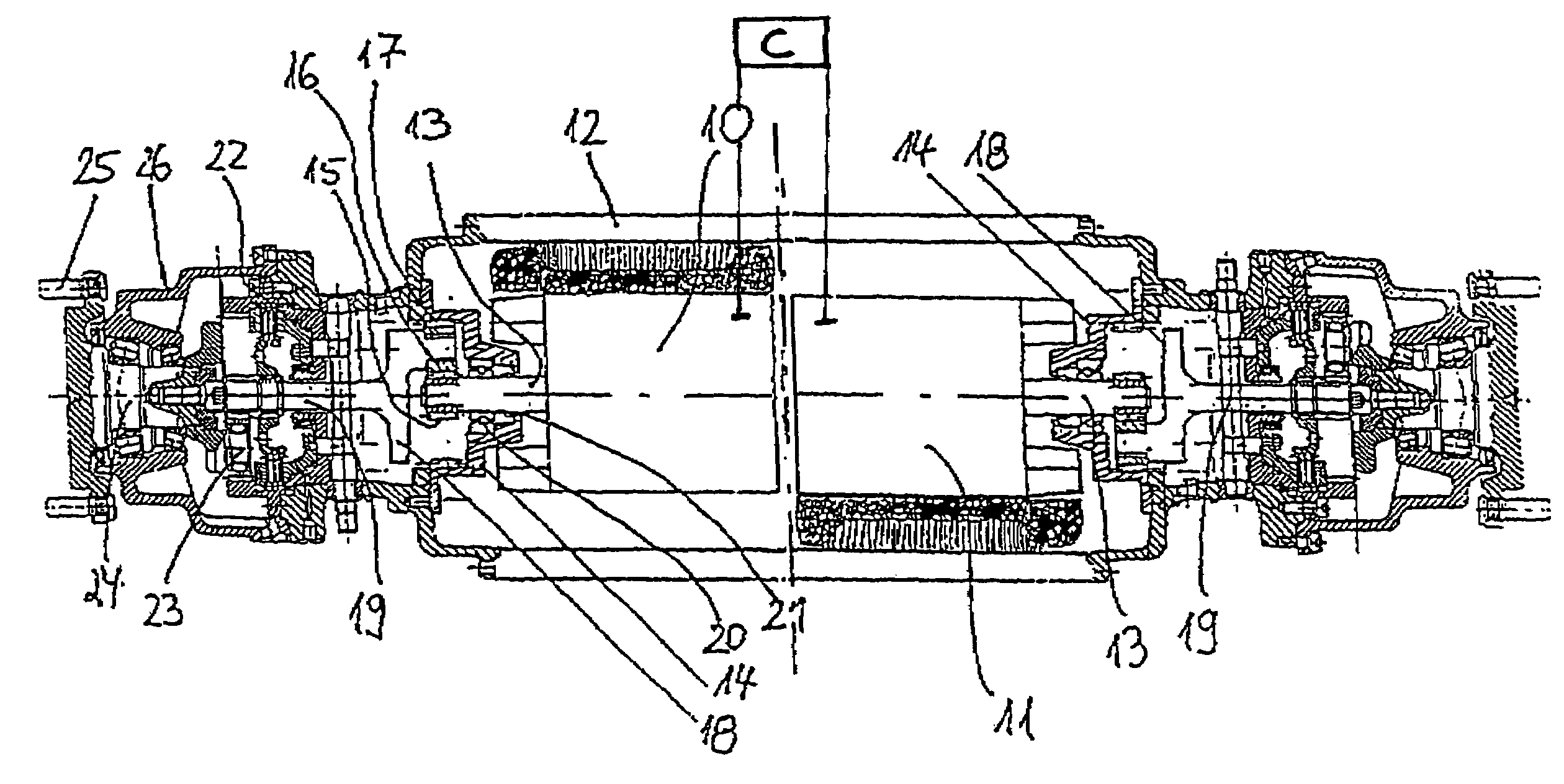
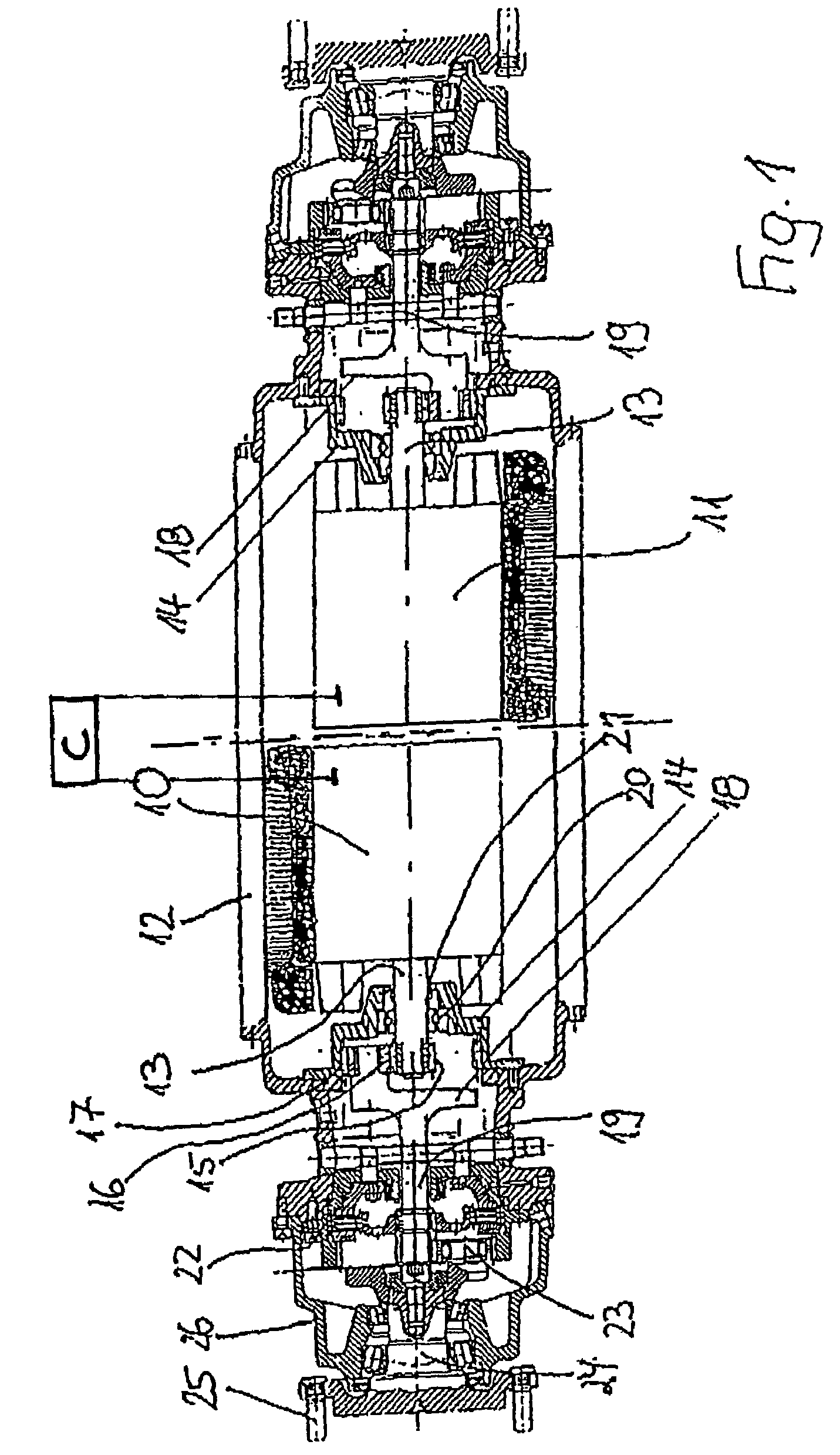
[0017]Disposed in a common housing 12, which is connected with the chassis of the vehicle, are two asynchronous motors 10, 11 that are separate from one another, whereby each motor 10, 11, via a drive arrangement that will be described subsequently, drives an individual wheel that is disposed on the drive axle. The operating performances of the two asynchronous motors 10, 11 are controlled by a common control means C, whereby, for example, speed differences of the wheels that occur when traveling through curves are compensated for by the control means.

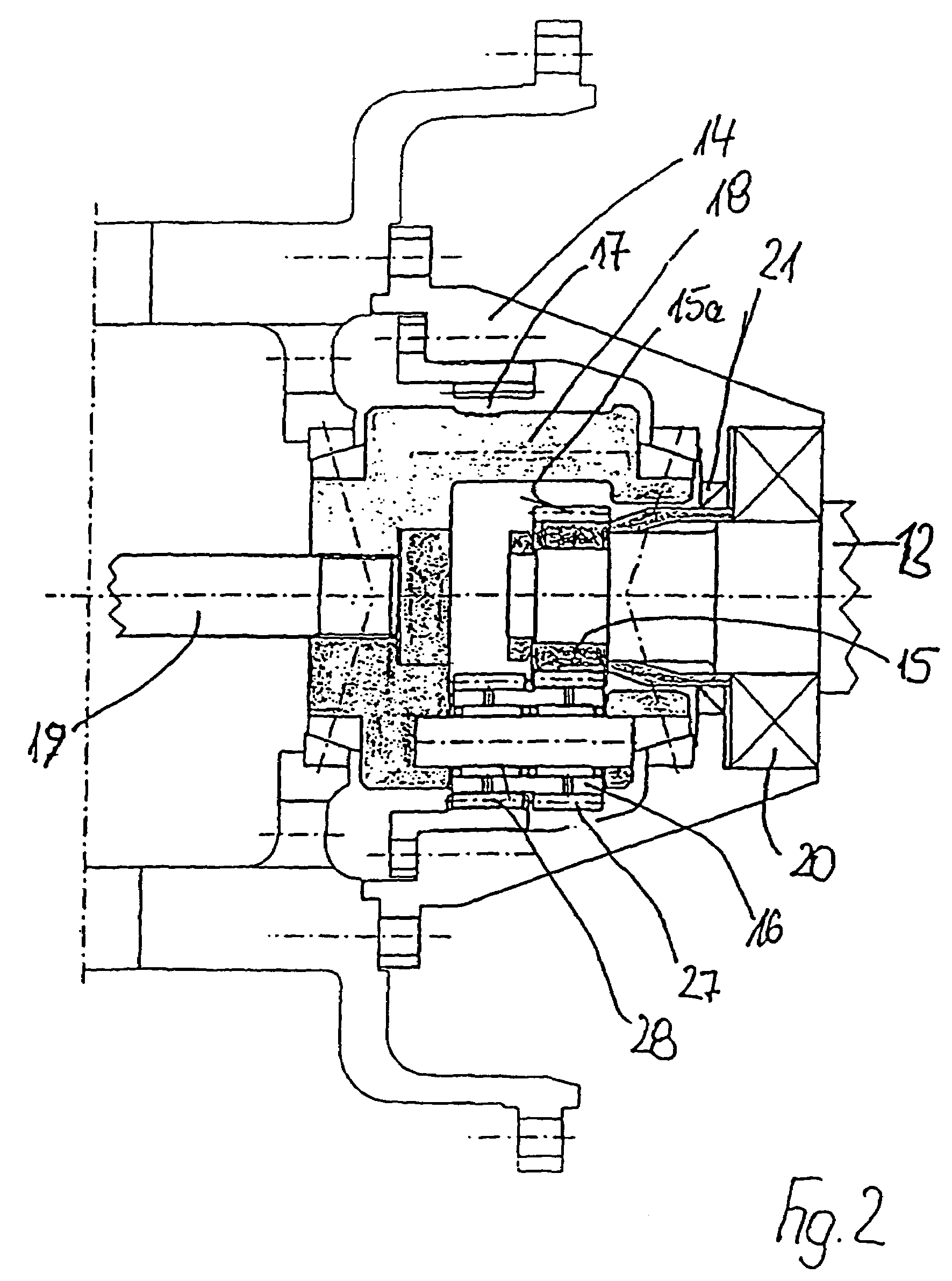
[0018]The motor shaft 13 of each individual asynchronous motor 10, 11 extends into a gearbox 14 of the gearing stage, which is provided for the connection of the motor shaft 13 with the downstream drive shaft 19, and which comprises a central or sun gear 15 disposed on the motor shaft 13, planet pinions 16 disposed on a planet carrier 18, as well as a hollow or internal toothing 17 formed on the inner side of the gearbox 14. The planet...


PUM


Abstract

The invention relates to a driving axle for electric motor-driven vehicles provided with at least one electric motor mounted on the axle and drive shafts driven by the motor shaft thereof with a planetary gear step inserted therebetween, connected to the output shafts bearing the wheels resting on the drive axle with a braking device and another planetary gear inserted therebetween. The invention is characterised in that two controlled asynchronous motors (10, 11) are disposed on the axle, said motors working separately and being controlled by a common control in the working functions thereof. The motor shafts (13) of both asynchronous motors (10, 11) are connected respectively by the planetary gear step (15, 16, 17) to the drive shaft (19) driving the downstream output shaft (24).

Description

BACKGROUND OF THE INVENTION[0001]The invention relates to a drive axle for electric motor driven vehicles having at least one electric motor disposed on the axle and having drive shafts that are driven by the motor shafts thereof accompanied by interposition of a planetary gearing stage, which drive shafts are connected with the output shafts that carry the wheels seated on the drive axle, accompanied by the respective interposition of a brake assembly as well as a further planetary gearing.[0002]A drive axle having the aforementioned features is disclosed in DE 200 10 563 U1. With the known axle a single three-phase motor is provided as a drive for both drive shafts, and the output shafts that are coupled thereon accompanied by the interposition of a brake assembly and a planetary gearing, and which drive the wheels seated on the axle; the single motor shaft of the three-phase motor is connected with the two drive shafts, accompanied by the interposition of a differential gearing, ...

Claims


Application Information

Patent Timeline
IPC IPC(8): F16H3/72B60K1/02B60K7/00B60K17/04H02K7/08H02K7/116H02K16/00
CPCB60K1/02B60K7/0007B60K17/046H02K16/00H02K7/116B60K2007/0092H02K7/085B60K2007/0038B60L7/24B60L15/2036B60L2220/42B60L2220/50Y02T10/72Y02T10/64
Inventor KEUTH, KARL-HEINZ
Owner HARLAN GLOBAL MFG
Why Eureka
Try Eureka