
Gas supply device for internal combustion engine and control method for the same

a technology of internal combustion engine and gas supply device, which is applied in the direction of electric control, combustion-air/fuel-air treatment, machines/engines, etc., can solve the problems of insufficient membrane differential pressure of conventional devices, inability to supply oxygen-enriched air or nitrogen-enriched air to combustion chambers, etc., to achieve the effect of improving fuel economy and no waste of energy

Active Publication Date: 2019-10-22
TOYOTA JIDOSHA KK
View PDF14 Cites 0 Cited by
  • Summary
  • Abstract
  • Description
  • Claims
  • Application Information

AI Technical Summary

Benefits of technology

Enables the efficient supply of oxygen-enriched or nitrogen-enriched air to the combustion chamber during non-supercharging engine operation, improving energy efficiency and fuel economy by generating necessary membrane differential pressure without relying on substantial pressurization or depressurization.

Problems solved by technology

However, when the internal combustion engine is operated in “a non-supercharging range where the supercharger cannot substantially carry out supercharging (compression and pressurization of the atmosphere)”, the conventional device cannot generate a sufficiently high membrane differential pressure.
That is, when the internal combustion engine is operated in the non-supercharging range, the conventional device cannot supply oxygen-enriched air or nitrogen-enriched air to the combustion chamber.

Method used


Image

  • Gas supply device for internal combustion engine and control method for the same
  • Gas supply device for internal combustion engine and control method for the same
  • Gas supply device for internal combustion engine and control method for the same

Examples


first embodiment

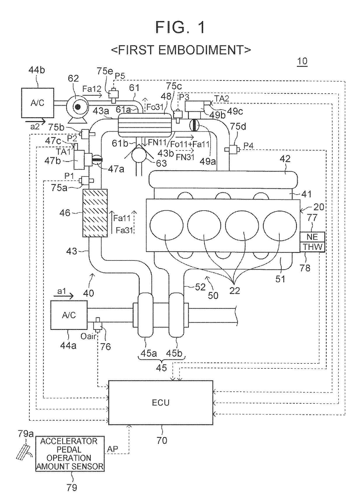
[0104]Next, the effect of the first gas supply device will be described. The first gas supply device has more excellent effects, which will be described below, than, for example, a typical gas supply device for an internal combustion engine 200 according to a reference example (a related art) of the present first embodiment of the disclosure shown in FIG. 7.

[0105]In the reference example, the intake air that has passed through the intercooler 46 is separated into oxygen-enriched air and nitrogen-enriched air in passing through the oxygen enrichment membrane module 48. The oxygen-enriched air is stored into an oxygen tank 221, and the nitrogen-enriched air is stored into a nitrogen tank 222. An ECU (not shown) provided in the reference example performs oxygen enrichment control and nitrogen enrichment control, which will be described below, by sending signals to throttle valve actuators 211b to 213b and appropriately controlling the throttle valve opening degrees of an oxygen throttl...

second embodiment

[0139]Next, a gas supply device according to the disclosure (hereinafter referred to as “a second gas supply device” in some cases) will be described. This second gas supply device is different from the first gas supply device only in the following respect.

[0140]As shown in FIG. 13, the second gas supply device is obtained by additionally providing the first gas supply device with a normal air intake pipe 90, and a third throttle valve 81a and third throttle valve actuator 81b that are disposed in the normal air intake pipe 90. The normal air intake pipe 90 constitutes an air passage through which intake air passes, between the intercooler 46 and a region downstream of the first throttle valve 47a, and establishes communication between a region downstream of the second throttle valve 49a and a region upstream of the surge tank 42.

The third throttle valve actuator 81b includes a third throttle opening degree sensor 81c for detecting a third throttle valve opening degree. The third th...

third embodiment

[0143]Next, a gas supply device according to the disclosure (hereinafter referred to as “a third gas supply device” in some cases) will be described. This third gas supply device is different from the first gas supply device only in the following respect. Incidentally, the characteristics of the third gas supply device can also be applied to the second gas supply device. As shown in FIG. 14, the third gas supply device is obtained by additionally providing the first gas supply device with an exhaust gas recirculation pipe (an EGR pipe) 100, an EGR valve 101a, an EGR valve actuator 101b, and an EGR cooler (an EGR gas cooling device) 102.

[0144]The exhaust gas recirculation pipe 100 constitutes an EGR gas passage through which EGR gas flows. One end of the exhaust gas recirculation pipe 100 communicates with the second air passage between a region downstream of the second throttle valve 49a and a region upstream of the surge tank 42. The other end of the exhaust gas recirculation pipe ...


PUM


Abstract

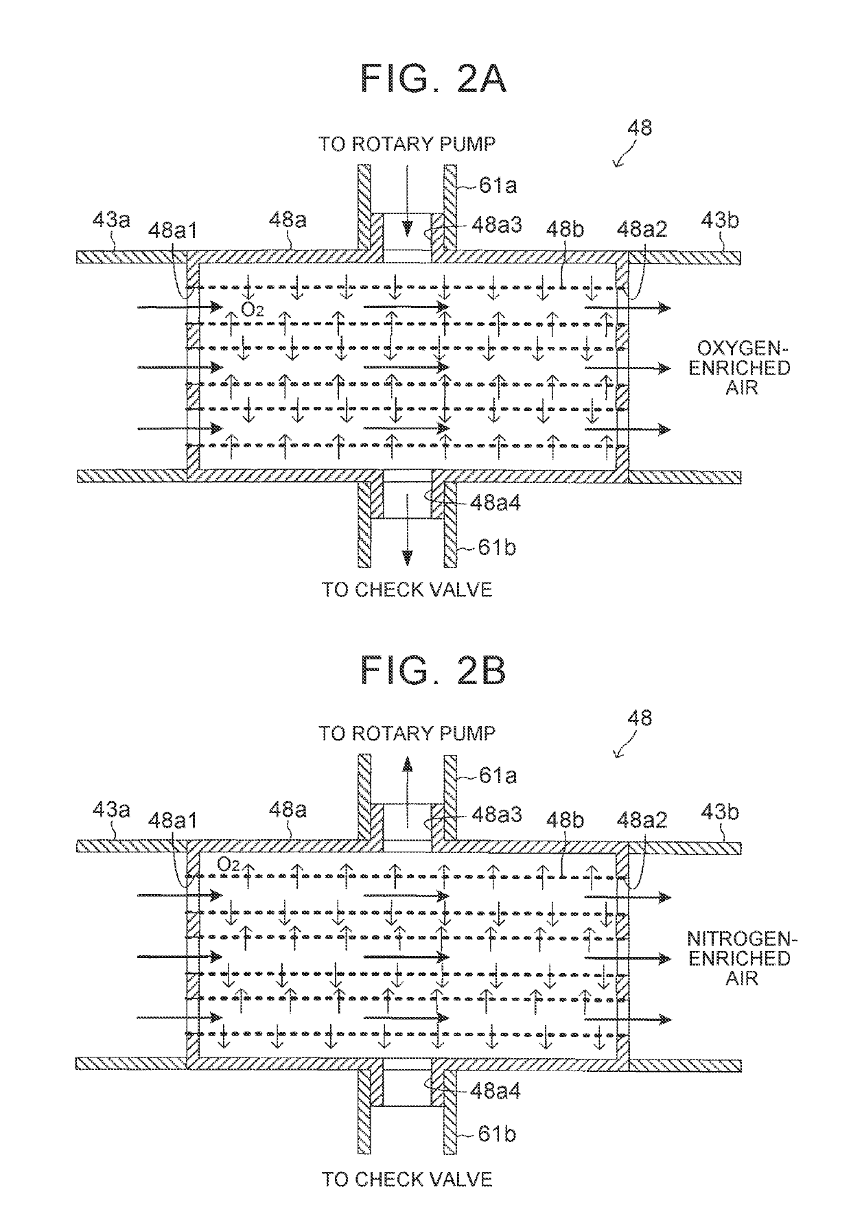
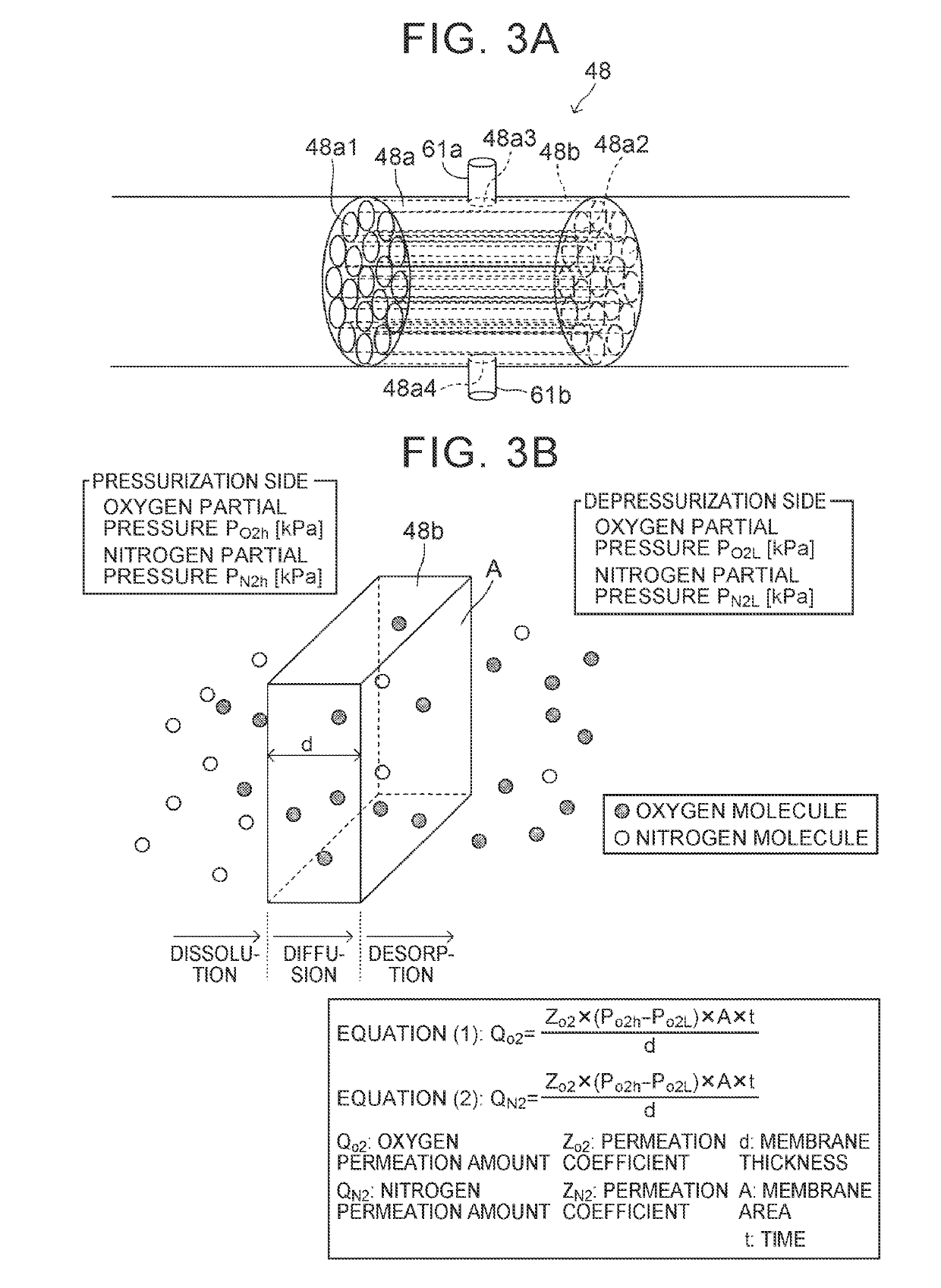
A gas supply device is equipped with an oxygen enrichment membrane module, a pump portion, and an electronic control unit. The electronic control unit performs oxygen enrichment control for merging the air supplied to a first space from a second space through the oxygen enrichment membrane and containing a higher concentration of oxygen than an atmosphere with the atmosphere that has flowed into the first space and supplying the merged air and atmosphere to a combustion chamber of the cylinders by driving the pump portion, and nitrogen enrichment control for discharging air containing a higher concentration of oxygen than the atmosphere to the second space from the first space through the oxygen enrichment membrane, producing air containing a higher concentration of nitrogen than the atmosphere in the first space, and supplying the air containing the higher concentration of nitrogen to the combustion chamber by driving the pump portion.

Description

CROSS-REFERENCE TO RELATED APPLICATIONS[0001]The disclosure of Japanese Patent Application No. 2017-100114 filed on May 19, 2017 including the specification, drawings and abstract is incorporated herein by reference in its entirety.BACKGROUND1. Technical Field[0002]The disclosure relates to a gas supply device for an internal combustion engine that reforms an atmosphere (air) into “oxygen-enriched air containing a higher concentration of oxygen than the atmosphere” or “nitrogen-enriched air containing a lower concentration of oxygen than the atmosphere”, and that supplies the reformed air to a combustion chamber.2. Description of Related Art[0003]As described in, for example, Japanese Patent Application Publication No. 2016-166602 (JP 2016-166602 A), one conventionally known gas supply device of this kind (hereinafter referred to as “a conventional device”) for an internal combustion engine is equipped with a supercharger (a turbocharger), a gas separation device, a first gas storag...

Claims


Application Information

Patent Timeline
Patent Type & Authority Patents(United States)
IPC IPC(8): F02M25/12F02D21/04F02D41/14F02B47/06F02D41/00F02M35/10F02B33/44
CPCF02M35/10157F02B33/44F02D41/0025F02D41/144F02M25/12F02D21/04F02D41/1441F02D41/1456F02D41/1475F02B47/06F02D41/0007F02M35/10255F02D2200/0406F02D9/1005F02D23/00F02M33/00Y02T10/12
Inventor KIKUCHI, KAZUKI
Owner TOYOTA JIDOSHA KK
Learn More