Gas reforming device

a technology gas chamber, which is applied in the field of gas reforming device, can solve the problems of large necessary energy, large heat loss, and large energy generated, and achieve the effect of efficient reforming, large necessary energy, and large heat loss

Active Publication Date: 2013-06-04
NGK INSULATORS LTD
View PDF14 Cites 0 Cited by
  • Summary
  • Abstract
  • Description
  • Claims
  • Application Information

AI Technical Summary

Benefits of technology

[0005]In consideration of the foregoing problems, it is an object of the present invention to provide a gas reforming device capable of low-damage processing for the object, and capable of efficient reformation.
[0023]In accordance with the present invention, the gas reforming device is provided, which is capable of processing the object with a low damage, and is capable of efficiently reforming the object.

Problems solved by technology

However, if the pulse voltage with the long pulse width is applied to between the anode and the cathode, then heat is generated and inflicts heat damage on an object.
Moreover, in the plasma reformer including the reactor with the parallel flat plate structure, in order to uniformly generate the electric discharge, necessary energy becomes large, and a heat loss also becomes large.
Furthermore, in the plasma reformer including the reactor with the parallel flat plate structure, an activation effect for the process gas differs between an inlet side and outlet side of the process gas, and accordingly, efficient reforming thereof is difficult.

Method used


Image

  • Gas reforming device
  • Gas reforming device
  • Gas reforming device

Examples


first embodiment

Bipolar-Type Plasma Reformer

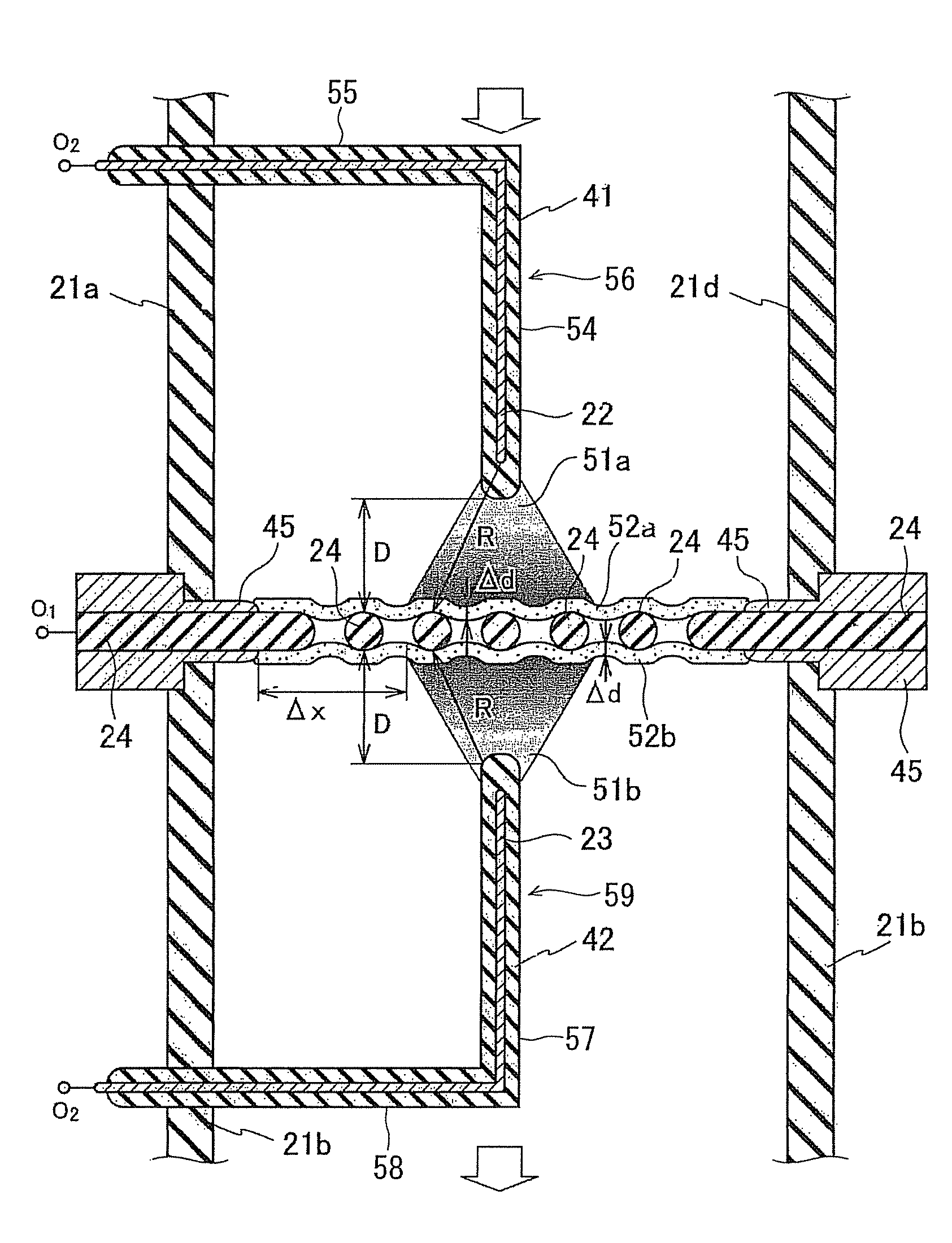
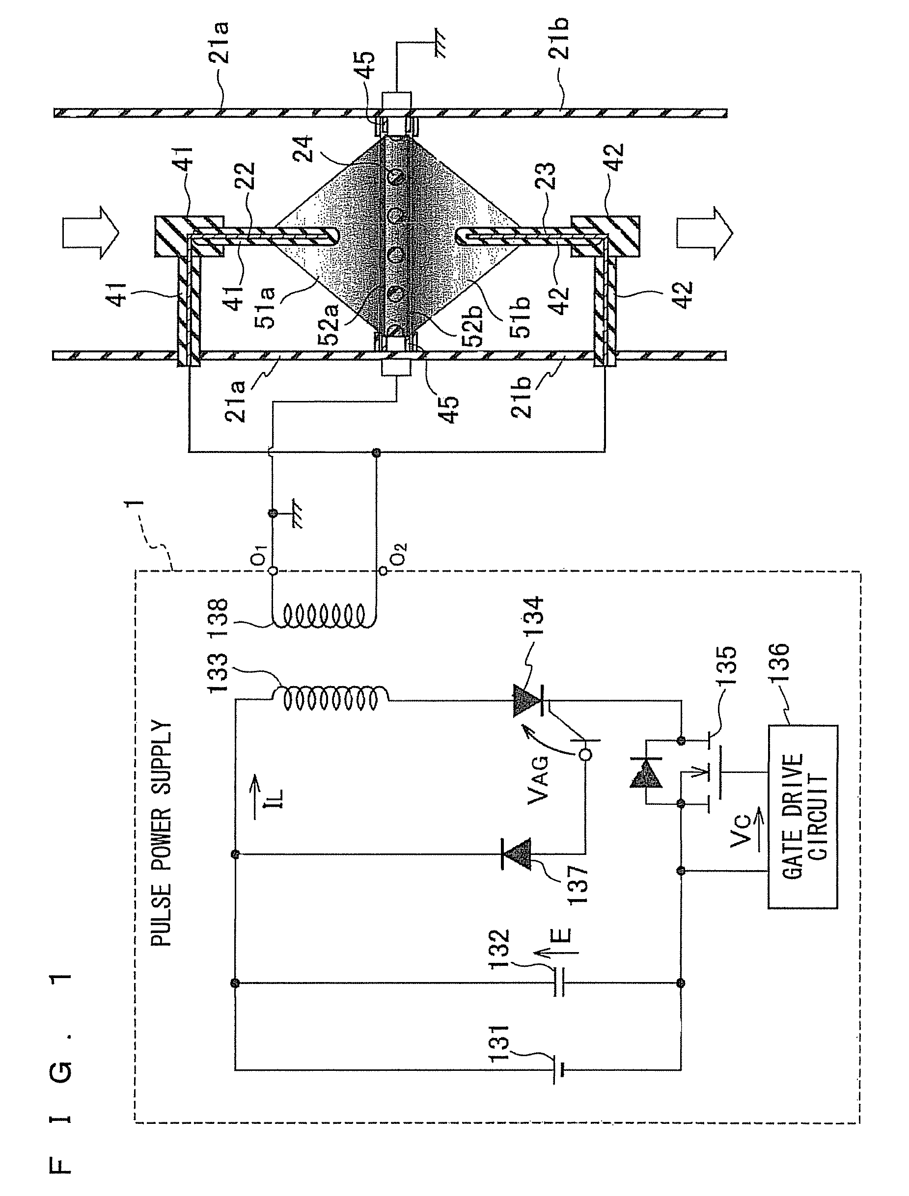
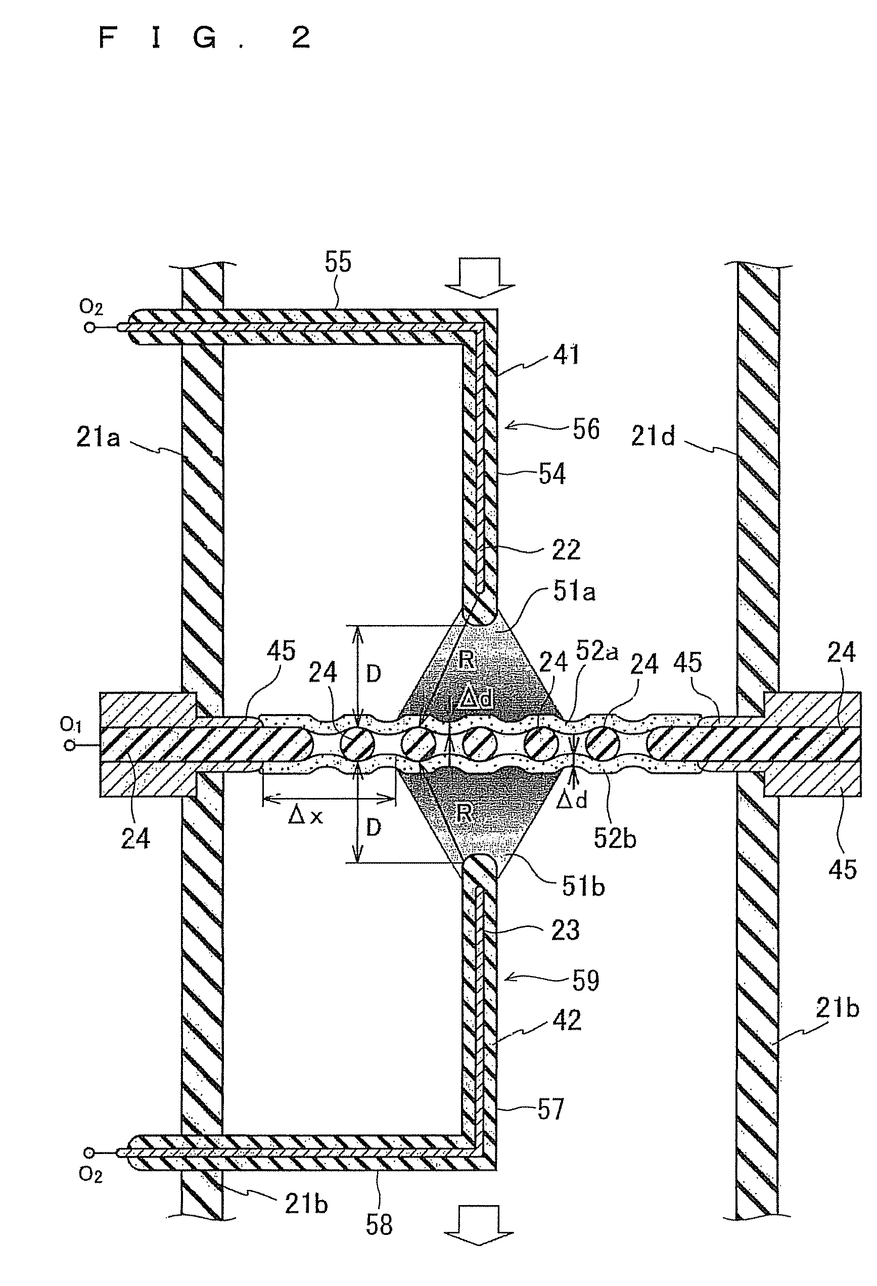
[0058]As shown in FIG. 1 and FIG. 2, a gas reforming device (plasma reformer) according to a first embodiment of the present invention includes: a first anode 22 and a second anode 23, which are arranged so as to be opposed to each other; and a common cathode 24 that is sandwiched between tip ends of the first anode 22 and the second anode 23 so as to be spaced apart therefrom, has a grid shape, has at least a surface thereof made of an insulator (dielectric), and includes grounding electrodes 45 on peripheral portions thereof. The grounding electrodes 45 made of conductor are brought into contact with end portions of ion sheath layers 52a and 52b spread on a surface of the common cathode 24, whereby a ground potential is given to the ion sheath layers 52a and 52b. Pulses with an equal polarity are applied to the first anode 22 and the second anode 23, and non-thermal equilibrium low-temperature plasma (hereinafter, simply referred to as “plasma”) is gene...

first modification example

[0100]As shown in FIG. 8, in a similar way to the structure shown in FIG. 2, a gas reforming device according to a first modification example of the first embodiment of the present invention includes: a first anode 22 and a second anode 23, which are arranged opposite to each other; and a common cathode 24 including a grid-like insulator sandwiched between respective tip ends of the first anode 22 and the second anode 23 so as to be spaced apart therefrom, and including grounding electrodes 45 on peripheral portions thereof. A ground potential is given to the common cathode 24, pulse voltages in which polarities are equal to each other are applied to the first anode 22 and the second anode 23, and bipolar-type plasmas are generated individually between the first anode 22 and the common cathode 24 and the second anode 23 and the common cathode 24.

[0101]The first anode 22 and the second anode 23 are inserted into a portion circular in cross section in a center portion of a gas reformi...

second modification example

[0102]As shown in FIG. 9 and FIG. 10, in a similar way to the gas reforming device shown in FIG. 2, a gas reforming device according to a second modification example of the first embodiment of the present invention includes: a plurality of first anodes 22ij and a plurality of second anodes 23ij, which are arranged opposite to each other; and a common cathode 24h that is sandwiched between respective tip ends of the plurality of first anodes 22ij and the plurality of second anodes 23ij so as to be spaced apart therefrom, includes a grid-like insulator, and includes grounding electrodes (not shown) on peripheral portions thereof. The plurality of first anodes 22ij and the plurality of second anodes 23ij have a bar shape, and are arranged parallel to one another. The respective tip ends of the plurality of first anodes 22ij and the plurality of second anodes 23ij are spaced apart from surfaces of the common cathode 24 by the same distance. The plurality of first anodes 22ij and the plu...


PUM


Abstract

A gas reforming device including: a flow passage forming body flow passage through which process gas flows; a cathode provided on a cross section of the flow passage; an anode provided apart from the cathode, and including a bar-like portion; and a pulse power supply that applies a pulse voltage between the cathode and the anode. The cathode includes: an opening array body that has at least a surface thereof made of an insulator, and has a planar structure in which openings through which the process gas passes are arrayed; and a grounding electrode provided on a peripheral portion of the flow passage. A tip end of the bar-like portion of the anode is located in an inside of the flow passage of the process gas, and is spaced apart from the opening array body in a direction parallel to a direction where the process gas flows.

Description

FIELD OF THE INVENTION[0001]The present invention relates to a gas reforming device, and particularly to a gas reforming device that activates process gas by non-thermal equilibrium low-temperature plasma.BACKGROUND ART OF THE INVENTION[0002]Heretofore, a parallel flat plate structure in which a flat plate-like anode and a flat plate-like cathode are opposed in parallel to each other has been known as a structure of a reactor which a gas reforming device (hereinafter, also referred to as a “plasma reformer”) includes, the gas reforming device activating process gas by non-thermal equilibrium low-temperature plasma and generating reform gas (Patent Document 1). In general, the anode and the cathode are embedded in flat plates as dielectrics. An electric discharge is generated between the anode and the cathode, which are embedded in the flat plates as the dielectrics.PRIOR ART DOCUMENTPatent Document[0003]Patent Document 1: Japanese Patent Application Laid-Open No. 2005-251444DISCLOSU...

Claims


Application Information

Patent Timeline
Patent Type & Authority Patents(United States)
IPC IPC(8): B01J19/08
CPCB01J19/088H05H1/24C01B3/342B01J2219/0811B01J2219/0826B01J2219/0839B01J2219/0894C01B2203/0861B01J2219/0875H05H1/46H05H2245/15
Inventor SHIMIZU, NAOHIROIMANISHI, YUUICHIROUHOTTA, SOZABURO
Owner NGK INSULATORS LTD
Why Eureka
Try Eureka