Liquid Fuel Reforming Device

a liquid fuel and reforming technology, applied in the direction of machines/engines, combustion air/fuel air treatment, non-metal raffination, etc., can solve the problems of remaining suspect, and achieve the effect of efficient reformation of liquid fuel

Inactive Publication Date: 2010-08-12
TAJIRI YASUO
View PDF3 Cites 2 Cited by
  • Summary
  • Abstract
  • Description
  • Claims
  • Application Information

AI Technical Summary

Benefits of technology

[0008]An object of the present invention is therefore to meet this need by providing a liquid fuel reforming device for installation at a desired location in an oil or other liquid fuel supply line such that the flow of oil or other liquid fuel passing through the liquid fuel reforming device causes at least one ceramic piece installed inside the liquid fuel reforming device to oscillate, thereby effectively bringing the liquid fuel into contact with the ceramic piece or pieces to realize efficient reformation of the liquid fuel.
[0015]Owing to its configuration as set out in the foregoing, the liquid fuel reforming device according to this invention offers the following merits:1. The liquid fuel reforming device of this invention enables supply of reformed oil and other liquid fuels with a device of simple structure comprising a main unit, at least one netlike member, and at least one ceramic piece. The simple structure of the device enhances durability and ease of maintenance. The configuration also facilitates replacement of the ceramic piece or pieces loaded in the main unit.2. The liquid fuel reforming device can supply a reformed oil and other liquid fuel, thereby enabling enhanced combustion efficiency of the liquid fuel.3. The number of ceramic pieces loaded into the main unit can be suitably adjusted to the optimum number for the properties of the liquid fuel to be reformed.4. The provision of the netlike body or bodies inside the main unit prevents the ceramic pieces from passing into the supply line, thereby ensuring stable operation of the device.5. Since the ceramic material used in the liquid fuel reforming device can be in the form of small ceramic pieces, the liquid fuel can be reformed by electrical charges produced by friction among the ceramic pieces and between the ceramic pieces and the liquid fuel.

Problems solved by technology

However, such devices, most of which are said to utilize the action of far infrared radiation, remain suspect because the liquids they reform are in complete thermal equilibrium with no energy transfer at normal temperatures.

Method used


Image

  • Liquid Fuel Reforming Device
  • Liquid Fuel Reforming Device
  • Liquid Fuel Reforming Device

Examples


Embodiment Construction

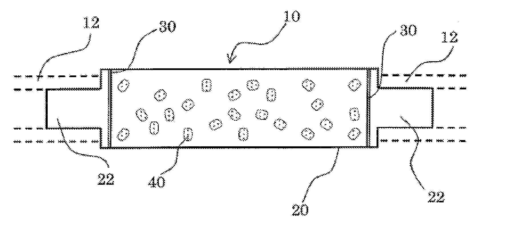
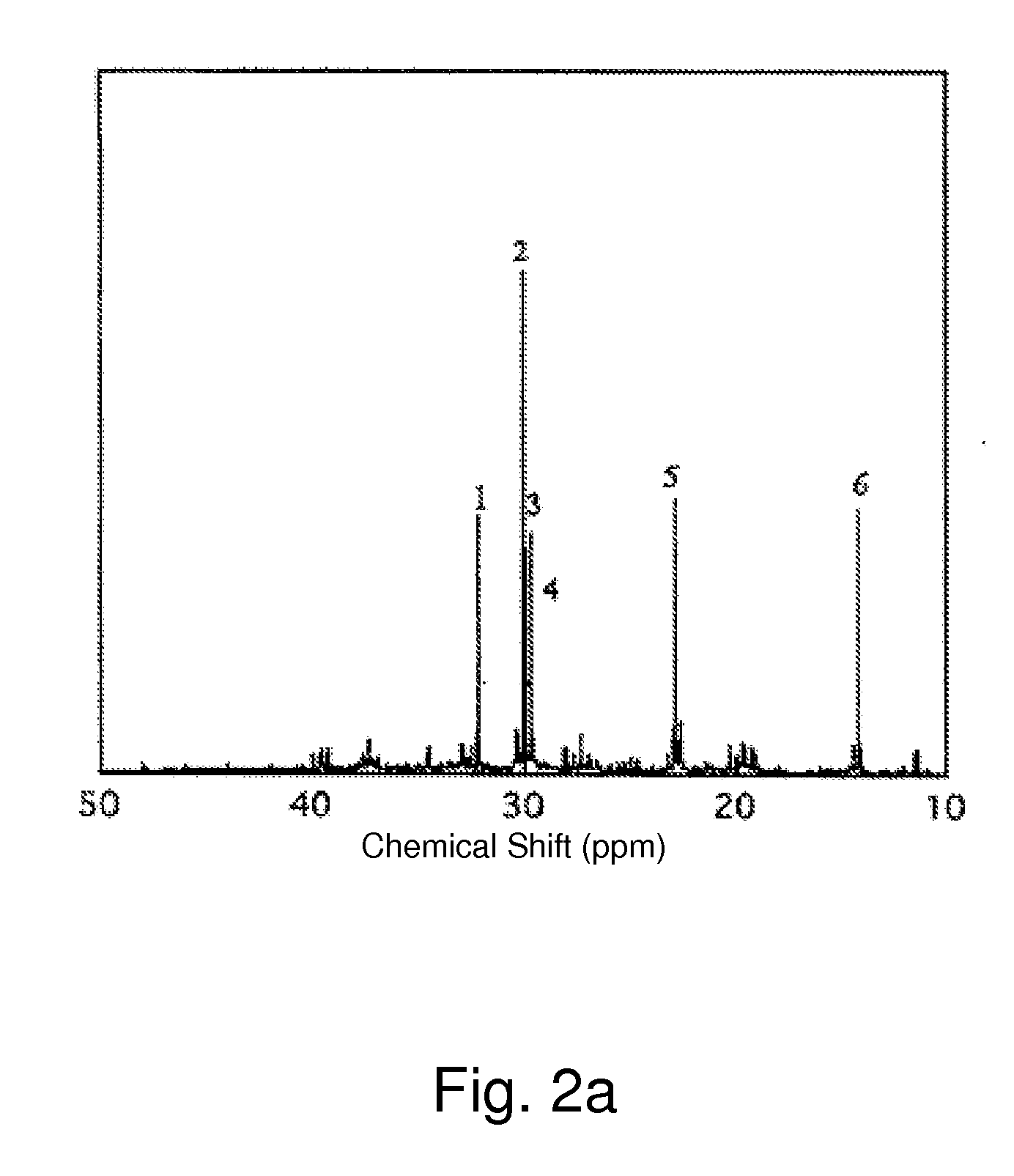
[0021]The liquid fuel reforming device according to the invention will now be explained in detail with reference to an embodiment shown in the drawings. FIG. 1 is a schematic diagram of the liquid fuel reforming device of the present invention. FIG. 2(a) shows the carbon-13 NMR spectrum of a heavy fuel oil. FIG. 2(b) is a graph showing the measured spin-lattice relaxation times of the main spectral peaks observed by carbon-13 nuclear magnetic resonance analysis for the heavy fuel oil in the cases where the liquid fuel reforming device was used and not used. FIGS. 3 and 4 are tables of measured results obtained when a heavy fuel oil-fired boiler was and was not equipped with the liquid fuel reforming device.

[0022]The liquid fuel reforming device of the invention, designated by the symbol 10 in the drawings, is composed of a tubular main unit 20, netlike bodies 30 and ceramic pieces 40.

[0023]The main unit 20 is equipped at its opposite ends with projecting connectors 22 for connection...


PUM


Abstract

A liquid fuel reforming device is provided which, when an oil or other liquid fuel is passed therethrough, efficiently produces reformed liquid fuel by causing the liquid fuel to make contact with ceramic pieces loaded in the liquid fuel reforming device. The liquid fuel reforming device, which is installed in an oil supply line for reforming oil or other liquid fuel, comprises a main unit formed as a tubular body provided with connectors projecting from its opposite ends for connection with the supply line and having a diameter larger than the diameter of the supply line, liquid fuel entering the main unit being reformed therein and then discharged; at least one netlike body provided between the main unit and at least one of the connectors; and at least one ceramic piece loaded into the tubular main unit for electrically charging the liquid fuel.

Description

BACKGROUND OF THE INVENTION[0001]1. Field of the Invention[0002]The present invention relates to a device for reforming a fluid, particularly to a liquid fuel reforming device for reforming heavy fuel oil and other liquid fuels by bringing the liquid fuel into contact with a ceramic body to produce an action on its molecular association.[0003]2. Description of Related Art[0004]Recent years have seen the development of ceramic water reforming devices that claim to be effective for preventing red rust deterioration and removing scale in water supply lines, and test data verifying these effects have been published. However, such devices, most of which are said to utilize the action of far infrared radiation, remain suspect because the liquids they reform are in complete thermal equilibrium with no energy transfer at normal temperatures.[0005]In addition, various activation devices have been developed and applied for patent. As an example can be cited the household water activation devi...

Claims


Application Information

Patent Timeline
Patent Type & Authority Applications(United States)
IPC IPC(8): F02M27/02
CPCB01J8/20B01J8/44B01J19/30B01J2208/00884B01J2219/30223B01J2219/30416F02M27/04C01B2203/0216C10G29/02C10G35/00C10L1/04C10L9/00C01B3/32
Inventor CHIKADA, HIDEKI
Owner TAJIRI YASUO
Why Eureka
Try Eureka