
Light emitting device and method of fabricating the same

a technology of light emitting device and light emitting device, which is applied in the direction of semiconductor devices, basic electric elements, electrical apparatus, etc., can solve the problems of deteriorating reducing the current injection area reducing so as to improve the luminous efficacy prevent deterioration of electrical characteristics of light emitting device.

Active Publication Date: 2019-09-03
SEOUL VIOSYS CO LTD
View PDF16 Cites 0 Cited by
  • Summary
  • Abstract
  • Description
  • Claims
  • Application Information

AI Technical Summary

Benefits of technology

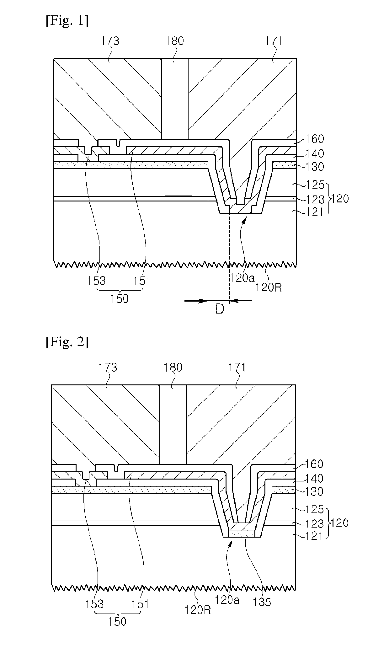
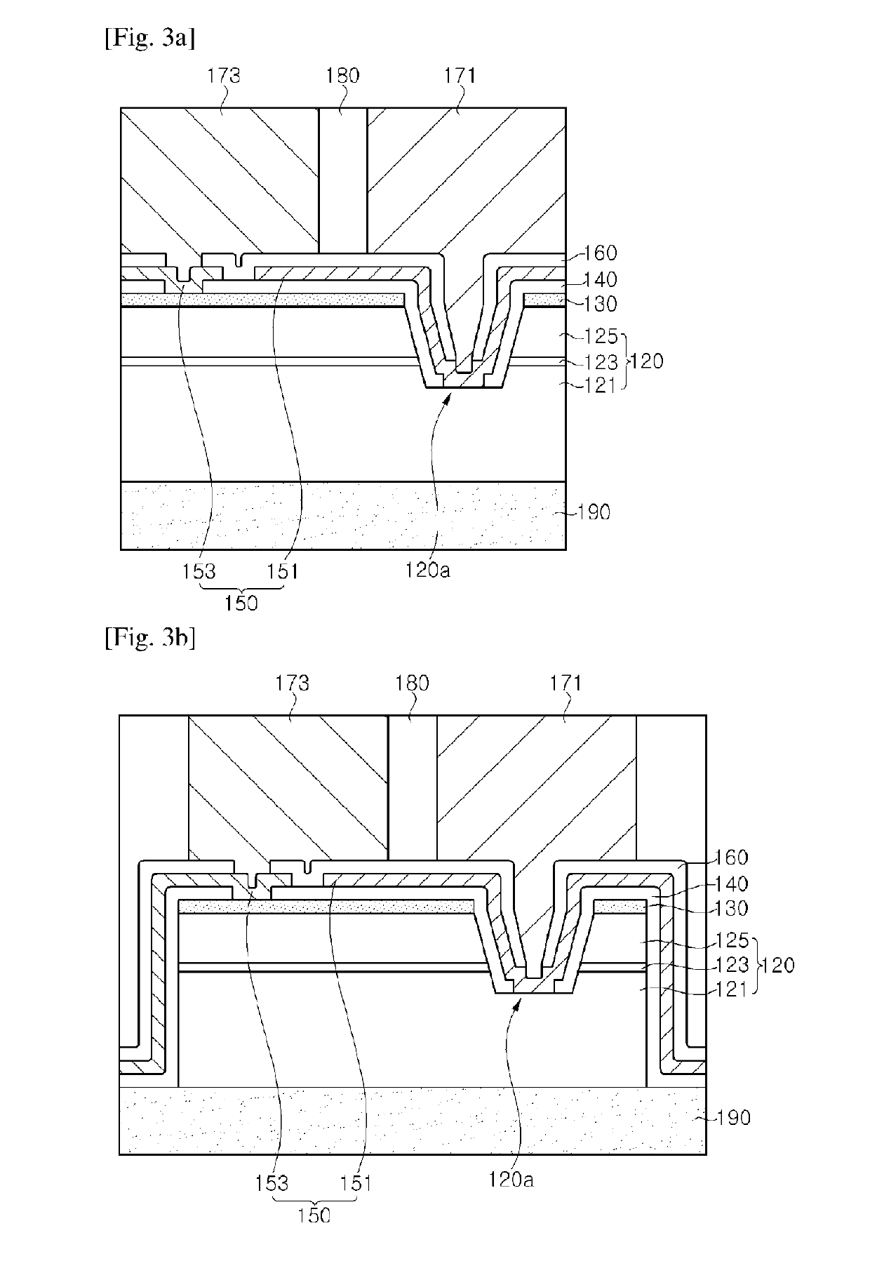
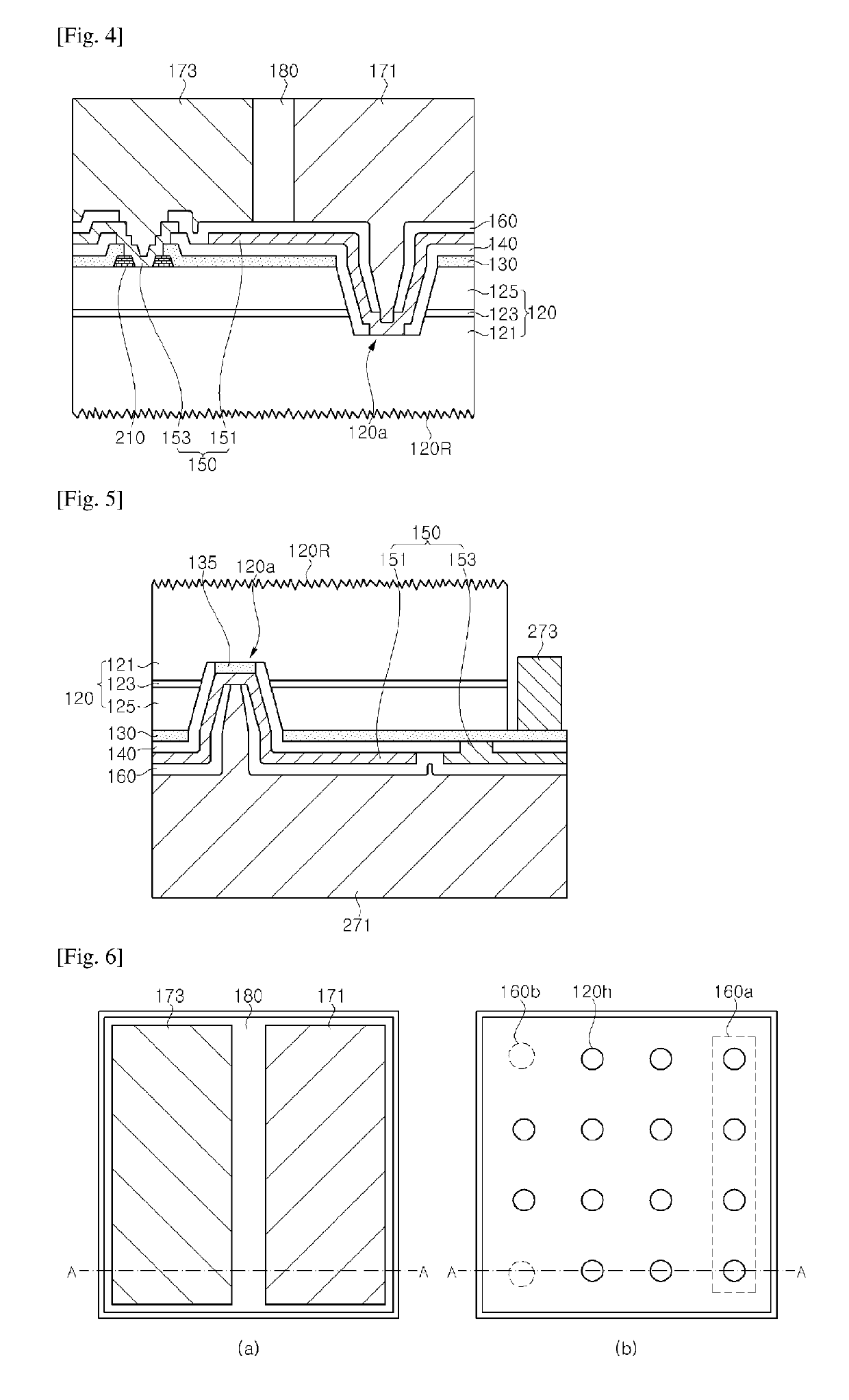
[0027]According to exemplary embodiments, a light emitting device including an omnidirectional reflector in which a transparent electrode, an insulation layer, and a metal layer are stacked may be provided. In the light emitting device, the transparent electrode is interposed between the metal layer and the semiconductor layer to prevent metal atoms from diffusing from the metal layer into the semiconductor layer, thereby preventing deterioration in electrical characteristics of the light emitting device, while improving luminous efficacy of the light emitting device through reflection by the omnidirectional reflector.

Problems solved by technology

First, in formation of the reflective electrode, a metal layer is subjected to patterning through photolithography, which makes it difficult to cover the overall surface of the p-type semiconductor layer with Ag due to process margin thereof. Namely, an ohmic contact area between the p-type semiconductor layer and an Ag electrode is decreased. As a result, a current injection area of the light emitting device is decreased and light is not reflected in a region in which the reflective metal is not formed, thereby deteriorating luminous efficacy of the light emitting device.
The diffused atoms deteriorate crystallinity of the semiconductor layer while increasing a possibility of current leakage, thereby deteriorating electrical and other characteristics of the light emitting device.

Method used


Image

  • Light emitting device and method of fabricating the same
  • Light emitting device and method of fabricating the same
  • Light emitting device and method of fabricating the same

Examples


Embodiment Construction

[0037]Hereinafter, exemplary embodiments will be described in more detail with reference to the accompanying drawings. The following embodiments are provided by way of example so as to fully convey the spirit of the present disclosure to those skilled in the art to which the present disclosure pertains. Accordingly, the present disclosure is not limited to the embodiments disclosed herein and can also be implemented in different forms. In the drawings, widths, lengths, thicknesses, and the like of elements can be exaggerated for clarity and descriptive purposes. When an element or layer is referred to as being “disposed above” or “disposed on” another element or layer, it can be “directly disposed above” or “directly disposed on” the other element or layer or intervening elements or layers can be present. Throughout the specification, like reference numerals denote like elements having the same or similar functions.

[0038]FIG. 1 is a sectional view of an exemplary light emitting devi...


PUM


Abstract

A light emitting device and a method of fabricating the same. The light emitting device includes: a light emitting structure including a first conductive type semiconductor layer, a second conductive type semiconductor layer, an active layer, and a partially exposed region of an upper surface of the first conductive type semiconductor layer; a transparent electrode disposed on the second conductive type semiconductor layer; a first insulation layer including a first opening and a second opening; a metal layer at least partially covering the first insulation layer; a first electrode electrically connected to the first conductive type semiconductor layer; and a second electrode electrically connected to the transparent electrode.

Description

CROSS REFERENCE TO RELATED APPLICATION[0001]This patent document is a 35 U.S.C. § 371 National Stage application of PCT Application No. PCT / KR2015 / 010874, filed on Oct. 15, 2015, which further claims the benefits and priority of prior Korean Patent Application No. 10-2014-0142576, filed on Oct. 21, 2014. The entire disclosures of the above applications are incorporated by reference in their entirety as part of this document.TECHNICAL FIELD[0002]The present disclosure relates to a light emitting device and a method of fabricating the same, and more particularly, to a light emitting device that exhibits excellent electrical and optical characteristics and has high reliability, and a method of fabricating the same.BACKGROUND ART[0003]Recently, with increasing need for small high output light emitting devices, demand for large flip-chip type or vertical type light emitting devices securing good heat dissipation efficiency has also be increased. In the flip-chip type or vertical type lig...

Claims


Application Information

Patent Timeline
Patent Type & Authority Patents(United States)
IPC IPC(8): H01L33/42H01L33/24H01L33/38H01L33/40
CPCH01L33/382H01L33/24H01L33/405H01L33/42H01L2933/0016H01L33/46
Inventor KIM, CHANG YEONPARK, JU YONGSON, SUNG SU
Owner SEOUL VIOSYS CO LTD
Learn More