Sealing of optical module with O-ring and liquid resin
a technology of optical modules and liquid resins, applied in the field of packaging structure of optical modules for video output devices, can solve the problems of small amount of saturated steam and easy condensation of dew, and achieve the effect of high-reliability packaging for optical modules
- Summary
- Abstract
- Description
- Claims
- Application Information
AI Technical Summary
Benefits of technology
Problems solved by technology
Method used
Image
Examples
first embodiment
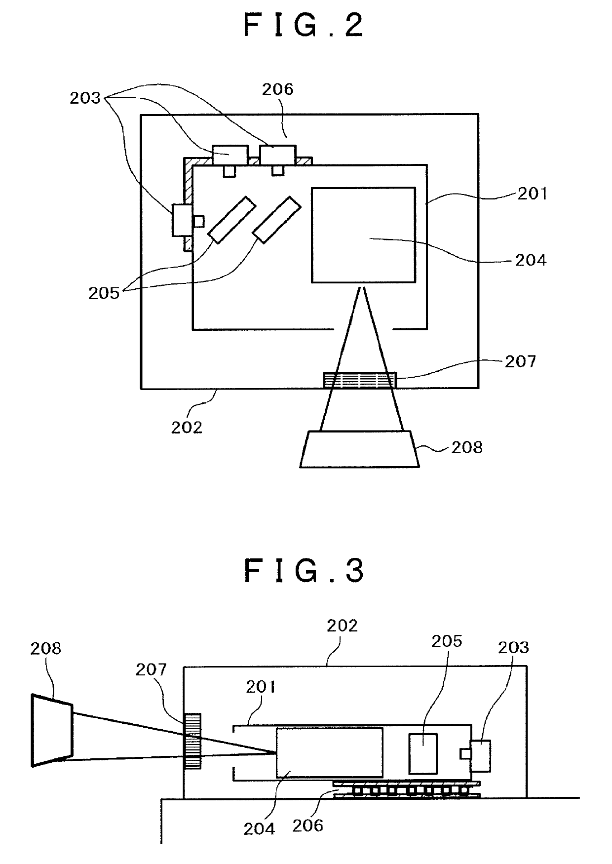
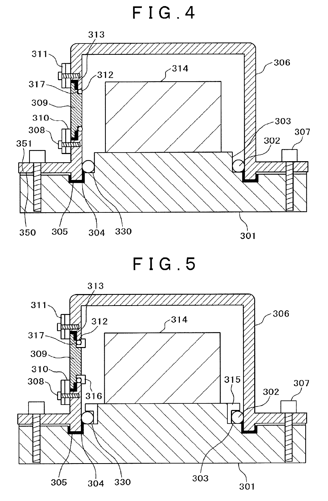
[0027]A first embodiment will be described with reference to FIG. 4. FIG. 4 is a side view showing an optical module according to the first embodiment. Note that the MEMS mirror 204, the laser diode 203, and the RGB combining mirror 205 shown in FIG. 3 are collectively illustrated as optical components 314. The Peltier element 206 and the lenses are not illustrated.
[0028]In the first embodiment in FIG. 4, a step 303 to dispose an O ring 302 on a peripheral portion of a pedestal 301 (base) is formed. The step 303 preferably has a height larger than a diameter of the O ring 302. This is because, in positioning performed with a screw 307 and a module cover 306 (will be described later), when the O ring 302 is transformed with pressure to partially enter the inside of the step 303, the airtightness is deteriorated. For this reason, the step having a height larger than the diameter of the O ring 302 is used to make it possible to prevent the O ring 302 from taking over the step 303. For ...
second embodiment
[0046]A second embodiment will be described below with reference to FIG. 5. FIG. 5 is a side view showing an optical module according to the second embodiment. The MEMS mirror 204, the laser diode 203, and the RGB combining mirror 205 which are shown in FIG. 3 are collectively illustrated as the optical components 314. The Peltier element 206 and the lens are not illustrated.
[0047]In the second embodiment, in addition to the constituent elements 301 to 314 according to the first embodiment shown in FIG. 4, an L-shaped O-ring torsion prevention stopper 315 is disposed on the outer peripheral side of the step 303 formed on the pedestal 301. Furthermore, an O-ring torsion prevention stopper 316 is disposed on the outer peripheral side of a step 317 of the emitting window 309. The O-ring torsion prevention stopper 316 is not always required. This is because, as described in the first embodiment, when the window is configured by a so-called permanently set window or a window fixed with a...
third embodiment
[0052]A third embodiment will be described below with reference to FIG. 6. FIG. 6 is a side view of an optical module according to the third embodiment. The MEMS mirror 204, the laser diode 203, and the RGB combining mirror 205 shown in FIG. 3 are collectively illustrated as the optical components 314. The Peltier element 206 and the lens are not illustrated.
[0053]In the third embodiment, of the constituent elements 301 to 314 according to the first embodiment shown in FIG. 4, the pedestal 301, the module cover 306, and the emitting window 309 are different in shape from those in the first embodiment.
[0054]In the first embodiment, the groove 305 and the step 303 are formed in the pedestal 301. The steps 317 are formed at two positions of the emitting window 309. Because of the complex shape, difficulty of processing disadvantageously increases, and processing costs may increase.
[0055]On the other hand, in the third embodiment, the pedestal 301 has no step, the groove 305 is formed t...
PUM
 Abstract
Description
Claims
Application Information
 - R&D
- Intellectual Property
- Life Sciences
- Materials
- Tech Scout
- Unparalleled Data Quality
- Higher Quality Content
- 60% Fewer Hallucinations
Browse by: Latest US Patents, China's latest patents, Technical Efficacy Thesaurus, Application Domain, Technology Topic, Popular Technical Reports.
© 2025 PatSnap. All rights reserved.Legal|Privacy policy|Modern Slavery Act Transparency Statement|Sitemap|About US| Contact US: help@patsnap.com


