Device for connecting the ends of pipes made of steel by means of an orbital welding process

Active Publication Date: 2018-10-16
SALZGITTER MANNESMANN LINE PIPE
View PDF22 Cites 3 Cited by
  • Summary
  • Abstract
  • Description
  • Claims
  • Application Information

AI Technical Summary

Benefits of technology

The invention is a device for connecting the ends of steel pipes by means of orbital welding. The device is designed to overcome disadvantages of other devices by being cost-effective, flexible, and easy to use with small time investment. The device can be used for already aligned pipes and reduces the required work area for the optical fiber. The device utilizes an angled optic and ball screw transmission for accurate positioning in Y-direction and Z-direction.

Problems solved by technology

A disadvantage is that two welding heads are required in order to weld the pipe along the entire circumference.
A disadvantage of this device is the complex construction with guide rings that are closed about the pipe and the elaborate alignment and centering of the pipe ends.
This makes the device very heavy and it can its use in mobile application is very difficult.
In addition the sequence of the welding process is very complex in which the pipe ends have to be inserted into the device and centered and subsequently the welded pipe has to be moved lengthwise out of the device.
In summary, no industrially applicable orbital guiding system exists in the state of the art that is optimally adjusted to the demands regarding quality and economical efficiency of the orbital welding.

Method used


Image

  • Device for connecting the ends of pipes made of steel by means of an orbital welding process
  • Device for connecting the ends of pipes made of steel by means of an orbital welding process
  • Device for connecting the ends of pipes made of steel by means of an orbital welding process

Examples


Embodiment Construction

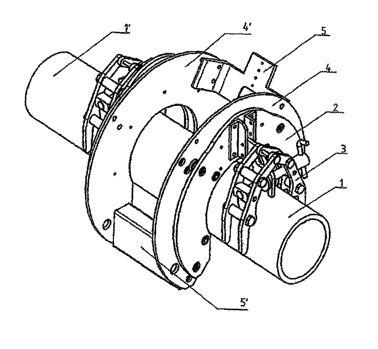
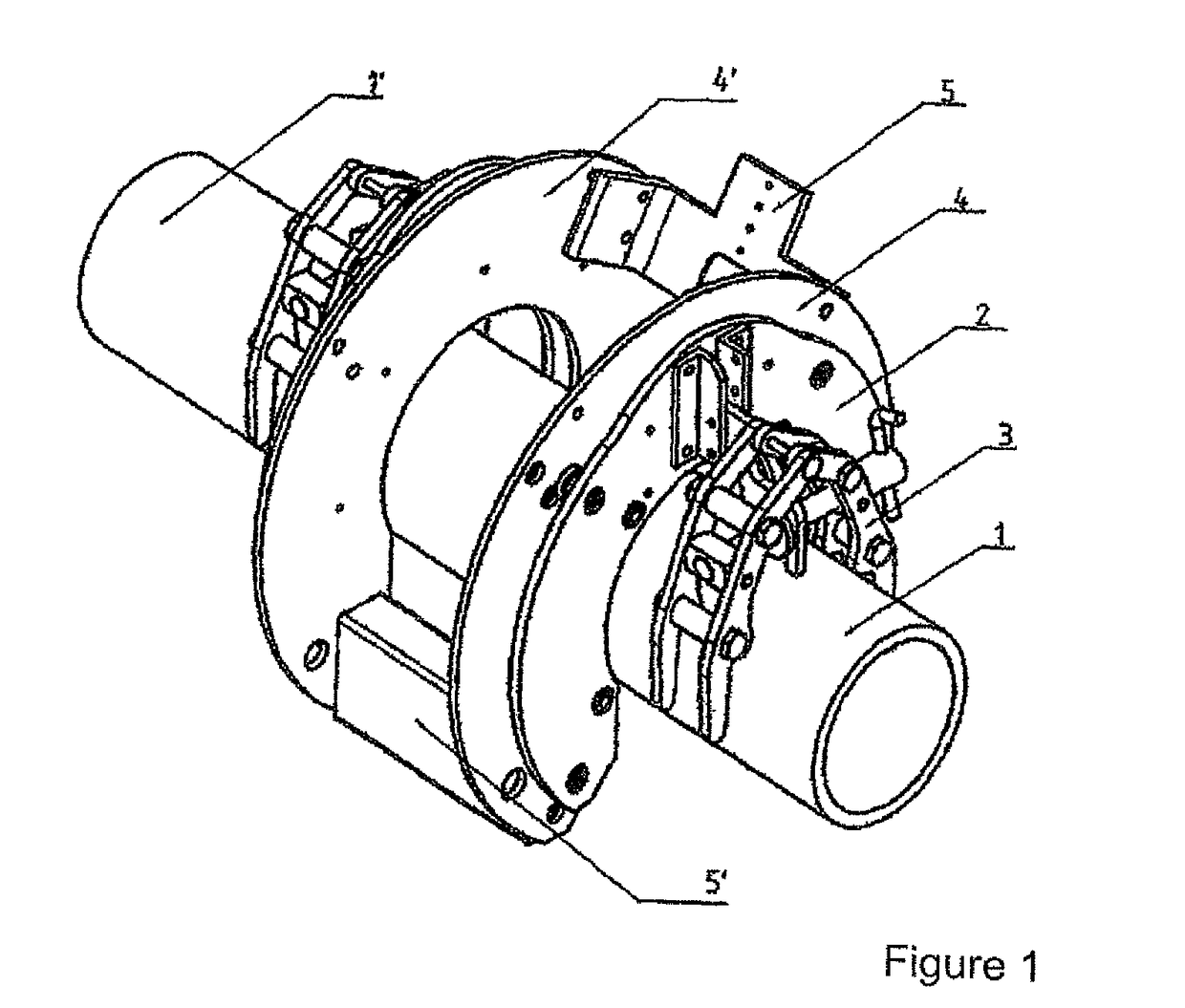
[0026]FIG. 1 illustrates the basic construction of the device according to the invention. It includes the two circular guide base plates 2, which are provided with a radial opening in order to be able to attach them onto the pipes 1, 1′ to be joined. The inner circular ring diameter is greater than the diameter of the pipes 1, 1′ to be welded in order to be able to perform an accurate alignment via the radial clearance for a centric circumferential movement of the welding and testing tools. For fastening the device on the ends of the pipes 1, 1′ clamping elements 3 are arranged on the outer welding groove-averted sides of the guide base plates 2, and are used to clamp the two guide base plates 2 with a respective pipe end via clamping elements 3.

[0027]A circular ring-shaped pivot bracket 4, 4′, which is also provided with a radial opening, is pivotally guided on each of the inner welding groove-facing sides of the guide base plates 2, so that the pivot brackets can also perform a ci...


PUM

PropertyMeasurementUnit
Angleaaaaaaaaaa

Abstract

A device for connecting the ends of pipes, which are aligned, tack-welded and made of steel, by an orbital welding process using a welding joint formed by the pipe ends and using tools which can be orbitally moved about the welding joint for welding and checking the seam. The device includes guide base plates placed on both sides at each pipe end in the region of the welding joint and rigidly clamped to the pipe ends. The guide base plates centrally have a circular recess with a radial opening for the feed-through of the pipes to be welded. The guide base plates include clamping elements rigidly connected to each guide base plate face facing away from the welding joint, and a frame for receiving the welding and checking tools, the frame rotatably mounted between the guide base plates and centrally pivotal about the pipe ends by at least 360°.

Description

CROSS-REFERENCES TO RELATED APPLICATIONS[0001]This application is the U.S. National Stage of International. Application No. PCT / DE2013 / 000179, filed Mar. 26, 2013, which designated the United States and has been published as International Publication No. WO 2013 / 152752 and which claims the priority of German Patent Application, Serial No. 10 2012 007 563.4, filed Apr. 10, 2012, pursuant to 35 U.S.C. 119(a)-(d).BACKGROUND OF THE INVENTION[0002]The invention relates to a device for connecting the ends of steel pipes by means of orbital welding.[0003]In particular, the invention relates to the welding of pipes, which may for example have wall thicknesses of 2 to 20 mm and a diameter of 60 to 1600 mm and which are connected to each other to form pipe lines by means of different welding procedures such as laser beam welding, combined laser beam / laser arc welding or electric arc welding. In the following, pipes are understood as circular pipes as well as hollow profiles with different cro...

Claims


Application Information

Patent Timeline
IPC IPC(8): B23K9/028B23K31/02B23K31/12B23K9/127B23K26/282G01N29/265B23K26/14B23K26/10B23K9/23B23K101/06B23K103/04
CPCB23K31/125B23K9/0286B23K9/1274B23K26/103B23K26/282B23K31/027G01N29/265B23K9/23B23K2103/04B23K2101/06G01N2291/267G01N2291/0289B23K26/348B23K37/053B23K31/02
Inventor KOCKS, HANS-JURGENWINKELS, JORNKEITEL, STEFFENNEUBERT, JANRUDE, SEBASTIAN
Owner SALZGITTER MANNESMANN LINE PIPE
Why Eureka
Try Eureka