Work machine

a work machine and tooling technology, applied in the field of machine tools, can solve the problems of deformation of the stability of the machine tool and increase the overall height, and achieve the effects of increasing the rigidity of the machine tool, maintaining the rigidity, and high rigidity and heavy bed

Active Publication Date: 2018-08-21
MAKINO MILLING MASCH CO LTD
View PDF12 Cites 1 Cited by
  • Summary
  • Abstract
  • Description
  • Claims
  • Application Information

AI Technical Summary

Benefits of technology

[0006]In the machine tool of Patent Document 1, the base defines a discharge hole extending from the front face to the rear face of the base, and therefore the feed screws are disposed above the base. Further, feed motors must be attached to the top ends of the ball screws because a space must be secured above the base for the movement of the vertically moving body. Accordingly, the gravity center of the machine tool becomes higher, because the relatively heavy feed motors are disposed at a point higher than the tool, and the guide rails for the vertically moving body are disposed above the discharge hole. As a result, the stability of the machine tool is degraded and the over-all height is increased by the feed motors mounted to the top of the machine. Further, the volume of the machine tool is increased, because the elements for supporting the feed motors must be manufactured to have a higher rigidity so as to bear the load acting on the supports.
[0007]The invention is directed to solve the above-described problems of the prior art, and the objective of the invention is to provide a highly rigid and compact machine tool which has gravity center set to a lower point compared with the prior art so as to increase the stability of the machine tool.
[0013]According to the invention, the arrangement of the feed screw of the vertically driving means disposed over the supporting means for supporting the bed on the floor, and the feed motor connected to the lower end of the feed screw allows the supporting means to receive directly the downward force acting on the bearing element of the feed screw and the motor bracket. Accordingly, the rigidity of the machine tool is increased. If the feed screw and the supporting means are apart from each other, a highly rigid and heavy bed is necessary. However, the above-described arrangement of the invention enables the bed to maintain the rigidity if its weight is reduced. Further, by disposing the relatively heavy feed motor at a lower portion of the machine tool, the gravity center is lowered and the overall height of the machine tool is reduced, resulting in a high stability. The increase in the rigidity and the stability of the machine tool allows the feed axes to move at a higher speed and accuracy. Furthermore, it contributes to downsizing of the machine tool.

Problems solved by technology

As a result, the stability of the machine tool is degraded and the over-all height is increased by the feed motors mounted to the top of the machine.

Method used


Image

  • Work machine
  • Work machine
  • Work machine

Examples


Embodiment Construction

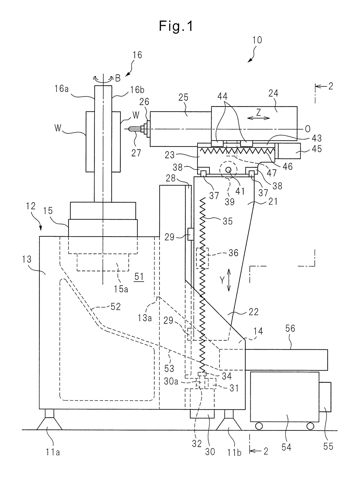
[0017]With reference to the drawings, an embodiment of the invention will be described below. FIG. 1 is a side view schematically showing the structure of a machine tool according to an embodiment of the invention. FIG. 2 is a rear view of the machine tool viewing in the direction of arrows 2-2 in FIG. 1. FIG. 3 is a perspective view schematically showing the exterior of the machine tool with a splashguard. In this specification, a front side of the machine tool is defined by the direction of the tip of a tool attached to the end of a spindle as described below.

[0018]In this embodiment, as an example, a machine tool 10 may be a four-axis horizontal machining center having liner feed axes extending in three orthogonal X-, Y- and Z-axes directions and a B-axis providing a rotary feed axis. The left-right direction (perpendicular to the plane of FIG. 1) of the machine tool 10 is defined as the X-axis, the vertical direction is defined as the Y-axis, and the front-rear direction (the le...


PUM

PropertyMeasurementUnit
forcesaaaaaaaaaa
gravityaaaaaaaaaa
stabilityaaaaaaaaaa

Abstract

A work machine includes: a bed having a table positioned on the upper surface thereof; sidewalls positioned to the left and right of the bed and projecting to the rear of the rear surface of the bed; support members for each supporting the bed in relation to a floor surface by using two points on the sidewalls to the left and right of the bed, and using at least one other point; a vertically moving body for moving along a pair of left and right vertical guides positioned in the vertical direction down to the vicinity of the floor surface on the rear surface of the bed; and a vertical drive means for moving the vertically moving body as one of the abovementioned relative movements, and having a pair of left and right feed screws positioned in parallel with the vertical guides.

Description

CROSS REFERENCE TO RELATED APPLICATIONS[0001]This application is a U.S. National Phase patent application of PCT / JP2012 / 066180, filed on Jun. 25, 2012, which is hereby incorporated by reference in the present disclosure in its entirety.FIELD OF THE INVENTION[0002]The invention relates to a machine tool for processing a workpiece by moving a tool attached to a spindle and the workpiece attached to a table relative to each other.BACKGROUND OF THE INVENTION[0003]Generally, in machine tools, there are various types of configuration for moving a spindle and a tale in X-, Y- and Z-axes. Depending on the configuration, X-, Y- and Z-axes moving bodies, X-, Y- and Z-axes guides, X-, Y- and Z-axes feeding drives and a chip remover are appropriately arranged.[0004]In a machine tool of Patent Document 1, the respective moving bodies movable in X-, Y- and Z-axes directions are disposed on a rear face of a base. A feeding mechanism for vertically moving a body along guide rails is disposed over t...

Claims


Application Information

Patent Timeline
Patent Type & Authority Patents(United States)
IPC IPC(8): B23Q3/18B23Q1/01B23Q1/44B23Q1/62B23Q5/40B23Q11/00
CPCB23Q1/015B23Q1/017B23Q1/44B23Q1/626B23Q11/0053B23Q11/0067B23Q5/40Y10T409/30392Y02P70/171Y02P70/10
Inventor SUZUKI, TOSHIHIROMAYUMI, KAZUYAKOBAYASHI, SATOSHI
Owner MAKINO MILLING MASCH CO LTD
Why Eureka
Try Eureka