Birdcage body coil for parallel transmit MRI

a mri and body coil technology, applied in the field of magnetic resonance (mr) imaging, can solve the problems of affecting the becoming more difficult, and even impossible to achieve the conventional degenerate tuning in practice, so as to achieve the maximum uniformity of the b1 field, the effect of improving the b1 field and maximum power-efficiency

Active Publication Date: 2018-07-17
KONINKLJIJKE PHILIPS NV
View PDF12 Cites 0 Cited by
  • Summary
  • Abstract
  • Description
  • Claims
  • Application Information

AI Technical Summary

Benefits of technology

[0032]In a preferred embodiment, the MR device further comprises a transmit unit for transmitting RF signals to the RF coil arrangement, wherein the transmit unit has a plurality of transmit channels, each transmit channel being connected to one RF drive port of the birdcage resonator. Therein, the number of transmit channels is equal to the number of rungs of the birdcage resonator. Driving the birdcage resonator of the invention via the independent transmit channels allows for significant improvement of the B1 field within the body of the examined patient. Preferably, each transmit channel comprises an RF power amplifier as source of an RF signal supplied via the respective transmit channel. RF shimming is enabled by individually adjusting the power and / or phase of the RF signal transmitted via each transmit channel. A maximum uniformity of the B1 field and maximum power-efficiency are achieved when all RF drive ports are supplied with RF signals with a quadrature phase distribution.

Problems solved by technology

However, as the MR frequency increases with increasing strength of the main magnetic (B0 field), this becomes more difficult due to conductive losses and wavelength effects within the body of the patient.
On examining the performance of a conventional birdcage resonator with respect to excitation uniformity it is observed that at high frequencies (>128 MHz) dielectric based standing wave mechanisms severely affect the B1 field uniformity.
It has been observed that in the case of a large bore design with a closely fitting RF screen it is difficult, even impossible, to achieve the conventional degenerate tuning in practice.

Method used


Image

  • Birdcage body coil for parallel transmit MRI
  • Birdcage body coil for parallel transmit MRI
  • Birdcage body coil for parallel transmit MRI

Examples


Embodiment Construction

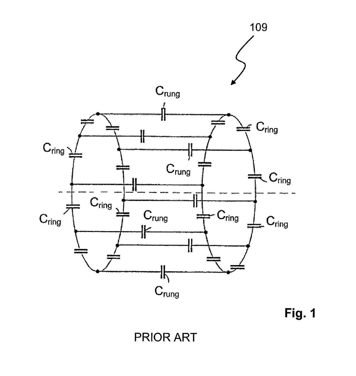
[0040]FIG. 1 shows the conventional design of a birdcage resonator 109 as it is commonly used in MR imaging. The birdcage resonator 109 comprises a plurality of rungs arranged along the circumference of a cylindrical examination volume. Each rung comprises a rung capacitance Crung. Two end rings are arranged at the opposite ends of the rungs, wherein each end ring comprises a plurality of ring capacitances Cring. Each ring capacitance Cring interconnects a pair of adjacent rungs. Each pair of adjacent rungs and interconnecting ring capacitances Cring forms a mesh of the birdcage resonator.

[0041]In a conventional MR imaging system, the birdcage resonator uses capacitance values Cring and Crung which realize the common so-called two-port birdcage tuning, in which only a single uniform resonant mode is tuned to the Larmor frequency.

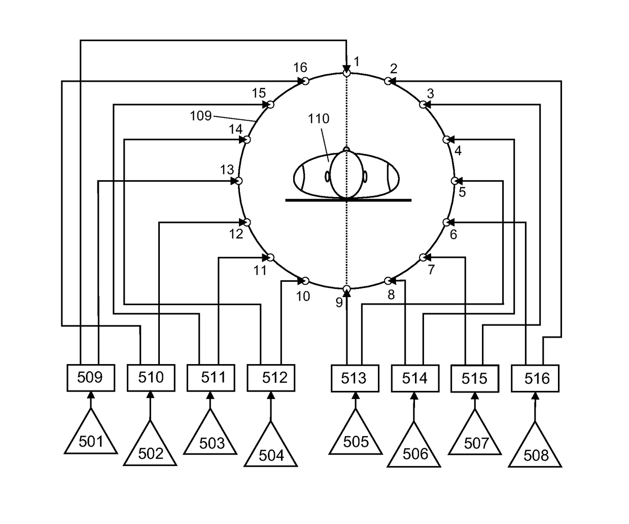
[0042]According to the invention, in contrast, the ratio of ring to rung capacitance values is chosen to realize N resonant modes, each tuned to the same re...


PUM


Abstract

A birdcage resonator (109) for MR imaging, surrounds an examination volume and includes a plurality of rungs (1-16) arranged in parallel to a longitudinal axis of the examination volume. Each rung (1-16) includes a rung capacitance (Crung). Two end rings are arranged at the opposite ends of the rungs (1-16), each end ring includes a plurality of ring capacitances (Cring). Each ring capacitance (Cring) interconnects a pair of adjacent rungs (1-16). Each pair of adjacent rungs and the interconnecting ring capacitances (Cring) form a mesh of the birdcage resonator. The ring capacitances (Cring) and the rung capacitances (Cring) are proportioned so that: —the birdcage resonator (109) has a plurality of resonant modes that are tuned to the same resonance frequency, and the meshes of the birdcage resonator (109) are electromagnetically coupled. An MR device (101) includes the birdcage resonator.

Description

CROSS-REFERENCE TO PRIOR APPLICATIONS[0001]This application is the U.S. National Phase application under 35 U.S.C. § 371 of International Application No. PCT / EP2013 / 068795, filed on Sep. 11, 2013, which claims the benefit of U.S. Provisional Patent Application No. 61 / 708,736 and European Patent Application No. 12186976.2, both filed on Oct. 2, 2012. These applications are hereby incorporated by reference herein.TECHNICAL FIELD[0002]The invention relates to the field of magnetic resonance (MR) imaging. It concerns a birdcage resonator for MR imaging and an MR device including a birdcage resonator.BACKGROUND OF THE INVENTION[0003]Image-forming MR methods which utilize the interaction between magnetic fields and nuclear spins in order to form two-dimensional or three-dimensional images are widely used nowadays, notably in the field of medical diagnostics, because for the imaging of soft tissue they are superior to other imaging methods in many respects, do not require ionizing radiatio...

Claims


Application Information

Patent Timeline
Patent Type & Authority Patents(United States)
IPC IPC(8): G01R33/34G01R33/3415G01R33/561G01R33/36
CPCG01R33/34076G01R33/3415G01R33/5612G01R33/561G01R33/3628
Inventor HARVEY, PAUL ROYSTON
Owner KONINKLJIJKE PHILIPS NV
Why Eureka
Try Eureka