
System and method for cryogenic purification of a feed stream comprising hydrogen, methane, nitrogen and argon

a technology of cryogenic purification and feed stream, which is applied in the field of integrated cryogenic purification system and method for chemical plants, can solve the problems of increasing capital and operating costs of complex and cumbersome conventional argon recovery processes

Active Publication Date: 2018-07-17
PRAXAIR TECH INC
View PDF20 Cites 3 Cited by
  • Summary
  • Abstract
  • Description
  • Claims
  • Application Information

AI Technical Summary

Benefits of technology

The present invention is a method for purifying a hydrogen, nitrogen, methane, and argon containing feed stream to produce a hydrogen and nitrogen containing synthesis gas, a methane fuel gas, and at least one nitrogen product. The method includes steps of conditioning the feed stream, directing the conditioned feed stream to a synthesis gas rectification column, vaporizing a methane-rich condensed phase stream, directing the vaporized stream to a nitrogen recovery system, warming a nitrogen-containing overhead vapor stream, and warming a methane-rich liquid bottoms stream. The method also includes steps of pre-purification of the crude feed stream, removing impurities, and using the methane-rich fuel gas as a reflux or a source of make-up nitrogen or refrigerant. The recovered hydrogen and nitrogen can be further utilized in downstream processes.

Problems solved by technology

The conventional argon recovery processes are relatively complex and involves multiple columns, vaporizers, compressors, and heat exchangers, as described for example in W. H Isalski, “Separation of Gases” (1989) pages 84-88.
While these waste gas processing solutions adequately recover the argon, hydrogen and nitrogen, they do so at additional capital and operating costs.

Method used


Image

  • System and method for cryogenic purification of a feed stream comprising hydrogen, methane, nitrogen and argon
  • System and method for cryogenic purification of a feed stream comprising hydrogen, methane, nitrogen and argon
  • System and method for cryogenic purification of a feed stream comprising hydrogen, methane, nitrogen and argon

Examples


Embodiment Construction

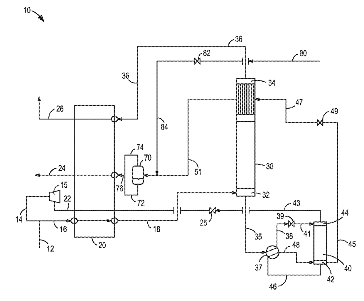
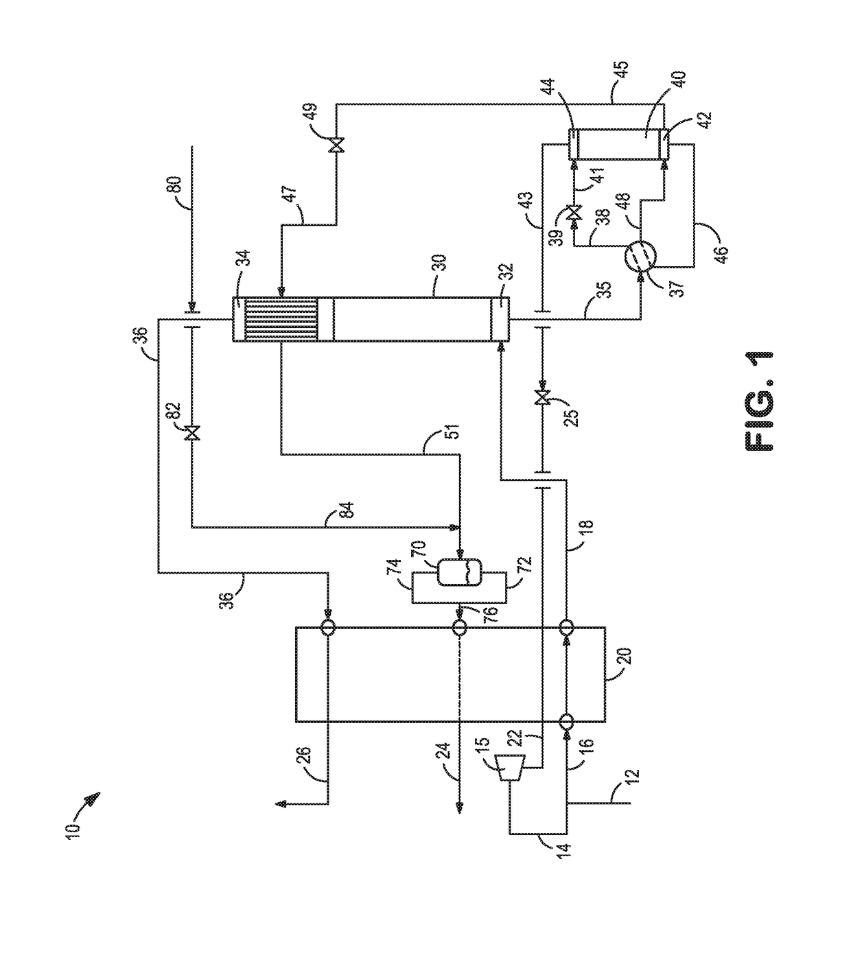
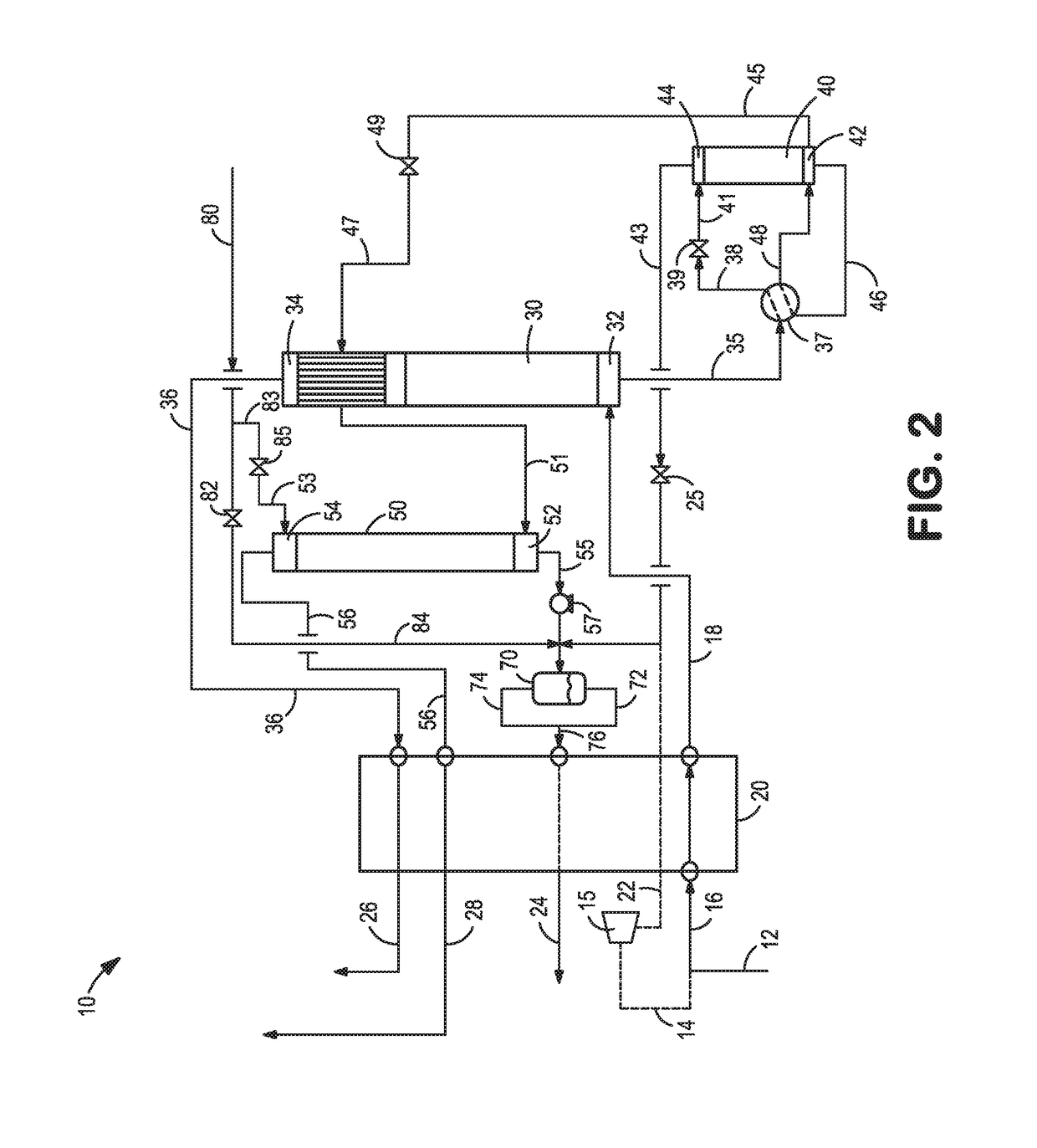
[0019]The following detailed description provides one or more illustrative embodiments and associated methods for cryogenic purification of a feed stream comprising hydrogen, nitrogen, methane and argon into its major constituents. The various embodiments include: (i) a cryogenic purifier system with stripping of excess hydrogen and recycling of the stripped hydrogen to the feed stream so as to increase the synthesis gas production; (ii) a cryogenic purifier system with enhanced recovery of nitrogen; (iii) a cryogenic purifier system with enhanced recovery of nitrogen and argon; and (iv) a cryogenic purifier system with an integrated nitrogen liquefier. Each of these embodiments will be described in the paragraphs that follow.

Cryogenic Purifier with Recycled Hydrogen Stream

[0020]Turning now to FIG. 1, a schematic representation of an integrated cryogenic purification system 10 is shown. As seen therein, a pre-purified feed stream 12 comprising hydrogen, nitrogen, methane and argon a...


PUM

PropertyMeasurementUnit
temperatureaaaaaaaaaa
pressureaaaaaaaaaa
adsorptionaaaaaaaaaa

Abstract

A system and method for cryogenic purification of a hydrogen, nitrogen, methane and argon containing feed stream to produce a methane free, hydrogen and nitrogen containing synthesis gas and a methane rich fuel gas, as well as to recover an argon product stream, excess hydrogen, and excess nitrogen is provided. The disclosed system and method are particularly useful as an integrated cryogenic purifier in an ammonia synthesis process in an ammonia plant. The excess nitrogen is a nitrogen stream substantially free of methane and hydrogen that can be used in other parts of the plant, recovered as a gaseous nitrogen product and / or liquefied to produce a liquid nitrogen product.

Description

TECHNICAL FIELD[0001]The present invention relates to an integrated cryogenic purification system and method for chemical plants, such as an ammonia plant. More particularly the present invention relates to a system and method for cryogenic purification and recovery of argon, hydrogen, and nitrogen from a crude synthesis gas feed stream comprising hydrogen, nitrogen, methane and argon to recover argon, as well as excess hydrogen and nitrogen.BACKGROUND[0002]The availability of low cost natural gas has led to the restart and construction of numerous ammonia production facilities throughout North America. Ammonia is typically produced through steam methane reforming. In the steam methane reforming process, air is used to auto-fire the reaction and to supply nitrogen for the ammonia synthesis reaction. In general, the steam methane reforming based process consists of primary steam reforming, secondary ‘auto-thermal’ steam reforming followed by a water-gas shift reaction and carbon oxid...

Claims


Application Information

Patent Timeline
Patent Type & Authority Patents(United States)
IPC IPC(8): F25J3/02C01B3/50F25J1/02F25J1/00C01C1/04F25J5/00
CPCF25J3/0223C01C1/0405F25J1/004F25J1/0015F25J1/0035F25J1/0037F25J1/0208F25J1/0237F25J1/0264F25J1/0288F25J3/0219F25J3/0233F25J3/0257F25J3/0276F25J3/0285F25J5/005C01B3/506F25J2270/904C01B2203/046C01B2203/068F25J2200/30F25J2200/70F25J2200/72F25J2200/74F25J2200/94F25J2200/96F25J2205/02F25J2205/30F25J2205/60F25J2210/04F25J2210/20F25J2210/42F25J2210/58F25J2210/62F25J2215/04F25J2215/20F25J2215/42F25J2215/58F25J2215/60F25J2220/02F25J2230/08F25J2230/30F25J2235/60F25J2240/12F25J2240/40F25J2245/02F25J2260/20F25J2270/02F25J2270/06F25J2270/12F25J2270/16F25J2270/42F25J2270/90Y02P20/52
Inventor HOWARD, HENRY E.
Owner PRAXAIR TECH INC
Learn More