
Bleed trigger monitor used in fuel cell system

rigger monitor technology, applied in the field of system and method for monitoring the anode bleed process of a fuel cell system, can solve the problems of low cell voltage, unstable fuel cell stack, and relatively high manufacturing cost of materials

Active Publication Date: 2012-03-06
GM GLOBAL TECH OPERATIONS LLC
View PDF1 Cites 0 Cited by
  • Summary
  • Abstract
  • Description
  • Claims
  • Application Information

AI Technical Summary

Benefits of technology

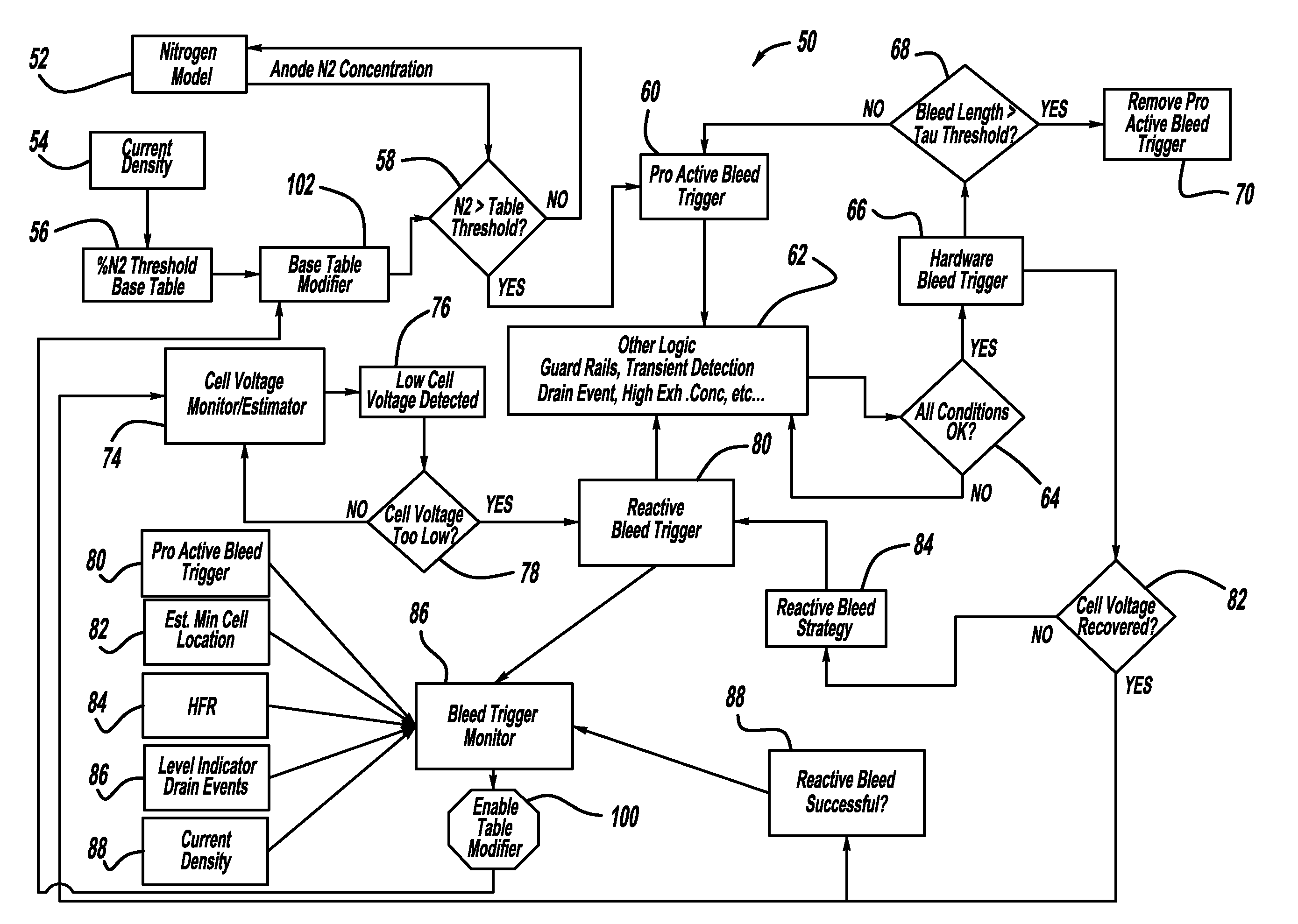
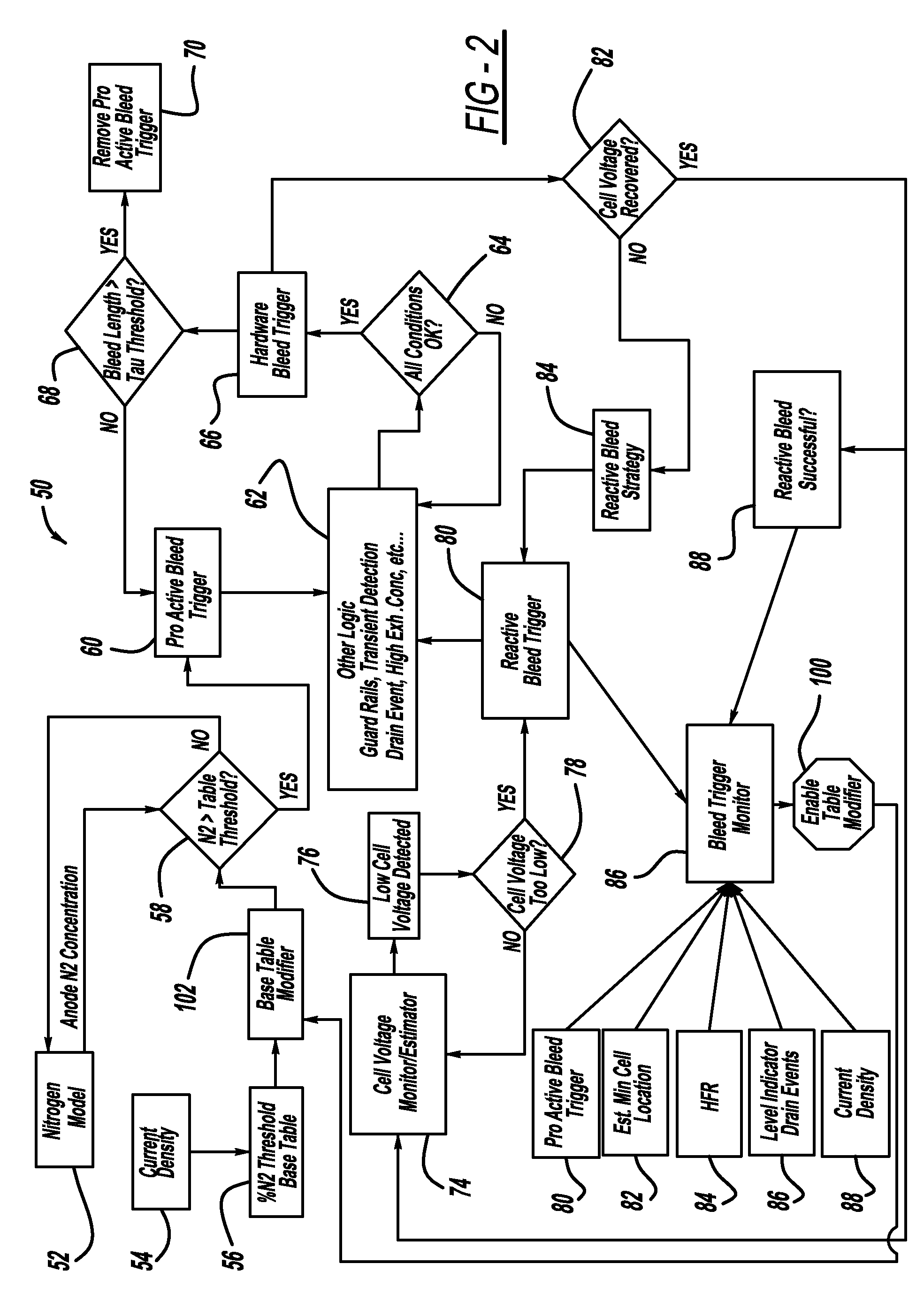
The present invention is a system and method for monitoring anode bleed trigger events and adjusting a proactive bleed schedule in a fuel cell system. The system uses a bleed trigger monitor algorithm to determine if the reactive bleeds are caused by excess nitrogen in the anode. The algorithm monitors the number of reactive bleeds and changes the proactive bleed schedule accordingly. The technical effect of this invention is to improve the efficiency and performance of fuel cell systems by optimizing the bleed schedule based on the accumulation of nitrogen in the anode side of the fuel cell stack.

Problems solved by technology

MEAs are relatively expensive to manufacture and require certain conditions for effective operation.
Nitrogen in the anode side of the fuel cell stack dilutes the hydrogen such that if the nitrogen concentration increases beyond a certain percentage, such as 50%, the fuel cell stack becomes unstable and may fail.
The primary cause of cell voltage loss is nitrogen buildup in the stack.
The higher the HFR the drier the stack, and the lower the HFR the more likely that excessive water in the anode is the cause of the reactive bleed.
However, as a fuel cell stack ages, cell performance decreases and nitrogen bleeds are required more often.
However, such an anode bleed strategy is obviously not efficient for the whole life of stack where the bleed duration typically would be too long and too frequent when the stack is new and too short and too infrequent when the stack is near the end of its life.
When the bleed is too long, the system operates inefficiently because a significant amount of hydrogen is being exhausted out of the anode exhaust.

Method used


Image

  • Bleed trigger monitor used in fuel cell system
  • Bleed trigger monitor used in fuel cell system
  • Bleed trigger monitor used in fuel cell system

Examples


Embodiment Construction

[0021]The following discussion of the embodiments of the invention directed to a system and method for monitoring the bleed events for bleeding the anode side of a fuel cell stack in a fuel cell system is merely exemplary in nature, and is in no way intended to limit the invention or its applications or uses.

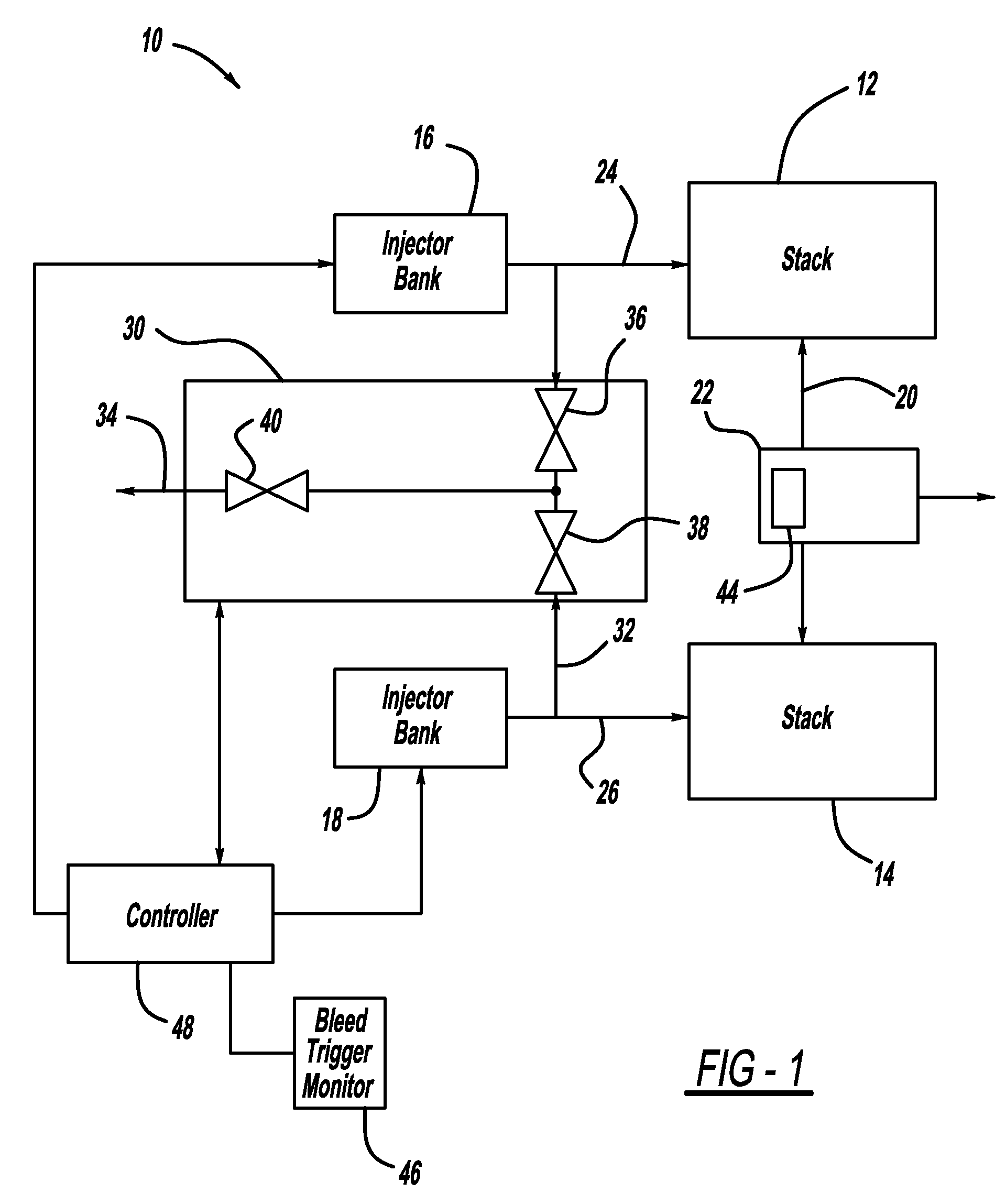
[0022]FIG. 1 is a schematic block diagram of a fuel cell system 10 including split fuel cell sub-stacks 12 and 14 that operate under anode flow shifting. When the flow is in one direction, an injector bank 16 injects fresh hydrogen into the anode side of the sub-stack 12 on anode input line 24. Anode gas that is output from the sub-stack 12 is sent to the sub-stack 14 on connecting line 20. When the flow is in the opposite direction, an injector bank 18 injects fresh hydrogen into the anode side of the sub-stack 14 on anode input line 26 that is output from the sub-stack 14 and sent to the sub-stack 12 on the line 20. A drain valve 22 is provided in the line 20 and can be used f...


PUM

PropertyMeasurementUnit
stack current densitiesaaaaaaaaaa
frequency resistanceaaaaaaaaaa
voltageaaaaaaaaaa

Abstract

A system and method for monitoring anode bleed trigger events and determining when to adjust a proactive bleed schedule in a fuel cell system. The system employs a bleed trigger monitor algorithm for monitoring proactive bleed and reactive bleeds that determines whether the reactive bleeds are caused by excess nitrogen in the anode. The algorithm monitors the number of reactive bleeds that are cause by nitrogen accumulation in the anode side of the fuel cell stack and changes the proactive bleed schedule in response thereto, if necessary.

Description

BACKGROUND OF THE INVENTION[0001]1. Field of the Invention[0002]This invention relates generally to a system and method for monitoring the anode bleed process of a fuel cell system and, more particularly, to a system and method for monitoring proactive and reactive bleeds of a fuel cell system that includes determining when the proactive bleed schedule should change to optimize the operation of the fuel cell system based on the number of reactive bleeds that have occurred as a result of an unexpected increase of nitrogen build-up in the anode-side of the fuel cell stack usually as a result of an aging system.[0003]2. Discussion of the Related Art[0004]Hydrogen is a very attractive fuel because it is clean and can be used to efficiently produce electricity in a fuel cell. A hydrogen fuel cell is an electrochemical device that includes an anode and a cathode with an electrolyte therebetween. The anode receives hydrogen gas and the cathode receives oxygen or air. The hydrogen gas is di...

Claims


Application Information

Patent Timeline
Patent Type & Authority Patents(United States)
IPC IPC(8): H01M8/04
CPCH01M8/04231H01M8/04649H01M8/04679H01M8/04746Y02E60/50
Inventor LERNER, SETH E.BURLEIGH, DARRELL W.
Owner GM GLOBAL TECH OPERATIONS LLC
Learn More