2D circulating gravity heat pipe

A gravity heat pipe and heat pipe technology, applied in the field of heat pipes, can solve problems such as the failure of the second-dimensional circulation loop

Inactive Publication Date: 2007-07-11
刘海云
View PDF0 Cites 4 Cited by
  • Summary
  • Abstract
  • Description
  • Claims
  • Application Information

AI Technical Summary

Problems solved by technology

Therefore, the existing heat pipe technology only utilizes the function of the first-dimensional circulation loop, that is, the design reflects the basic circulation process of the heat pipe work, so that the second-dimensional circulation loop does not play a role.

Method used


Image

  • 2D circulating gravity heat pipe
  • 2D circulating gravity heat pipe
  • 2D circulating gravity heat pipe

Examples


Embodiment Construction

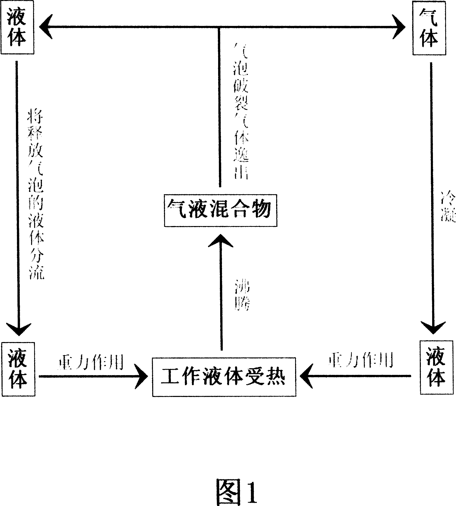
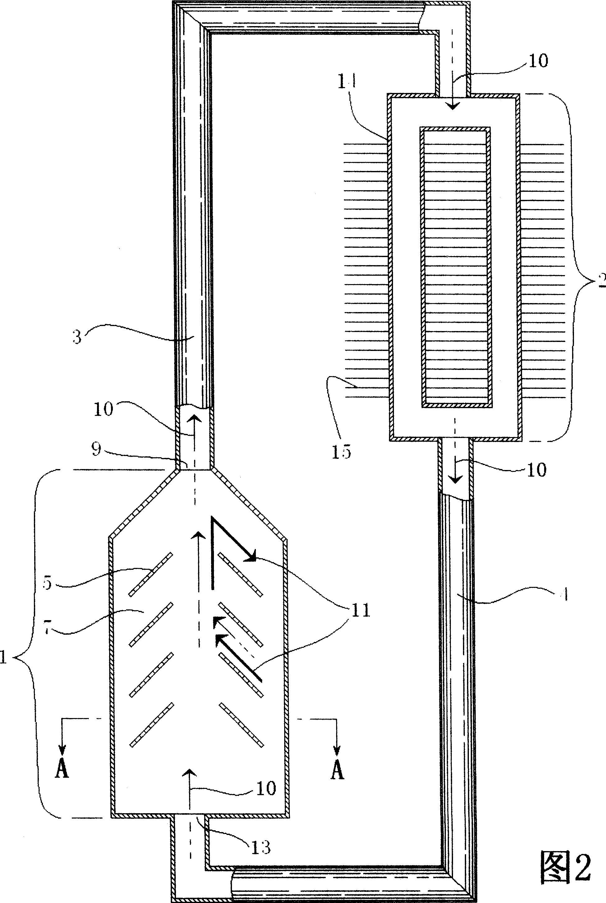
[0024] Referring to FIG. 2 , the heat pipe shown in the figure is a schematic structural diagram of the first embodiment of the present invention. In this embodiment, the heat pipe is composed of four parts: an evaporator 1 , a condenser 2 , an exhaust pipe 3 , and a liquid inlet pipe 4 . Referring to Fig. 2 and Fig. 3, the main feature of this heat pipe is that the heated wall 7 is one (or two opposite) side planes of the evaporator 1, and there are inclined guide fins 5 connected to the heated wall 7 in the evaporator 1 . As shown in FIG. 4 , the foaming arrangement 16 of the heated wall 7 is composed of tube cores 17 and grooves 18 . Next, we analyze the working process of the heat pipe. Referring to the first-dimensional circulation loop 10 shown by the dotted arrow in Fig. 2, when the heat pipe is working, the liquid in the evaporator 1 absorbs heat from the heated wall 7 and gasifies to generate bubbles, which float upward along the guide plate 5, and the bubbles float...


PUM


Abstract

The invention relates to a two-dimensional cycling gravity heat pipe with guiding device. It is characterized in that guiding device, such as guiding plate, guiding pipe, drain pipe, impeller and collecting liquid cover so on is set in the heat pipe to make liquid in heat pipe flow on the setting route in cycling for promoting liquid steaming in evaporator, quickening gas-liquid cycling and improving heat conducting speed. Certain working material is injected in the closed cavity where the heat pipe is pumped in vacuum. When the heat pipe works, two setting cycling routes exist in the heat pipe. One is the cycling route with mutual transformation between working gas and working liquid and the other is the flowing cycling route in the working liquid.

Description

technical field [0001] The invention is a heat pipe, which is mainly aimed at the improvement that gravity makes the condensed working liquid return to the heat pipe. Background of the invention [0002] With the development of science and technology, many devices have put forward higher requirements for heat dissipation or heat transfer components. Due to its superconductivity to heat, heat pipes are used more and more widely, and heat pipe technology has been greatly developed. The heat pipe is a working substance enclosed in it, and when the evaporator is heated and working, the liquid working substance in the evaporator absorbs heat and evaporates into a gas, and enters the condensation pipe under the action of the saturation pressure difference, and dissipates heat in the condensation pipe Condensation becomes liquid and flows back to the evaporator by capillary force or gravity to continue the cycle. Heat pipes usually require that there are no other substances that ...

Claims


Application Information

Patent Timeline
IPC IPC(8): F28D15/02
Inventor 刘海云
Owner 刘海云
Why Eureka
Try Eureka