
Method for making shadow mask of opposed-discharging type plasma plane display

A technology of a flat panel display and a manufacturing method, which is applied in the manufacturing of non-light-emitting electrodes, etc., can solve the problems of high difficulty, negative influence on the luminous efficiency of the display, and difficulty in controlling the width of the gas channel 23 and the depth.

Inactive Publication Date: 2007-06-13
MARKETECH INT
View PDF0 Cites 2 Cited by
  • Summary
  • Abstract
  • Description
  • Claims
  • Application Information

AI Technical Summary

Problems solved by technology

[0006] (1) The process of etching the barrier wall 122 and the gas channel 23 on both sides of the shadow mask 20 by double-sided etching is quite complicated and difficult, resulting in high production cost
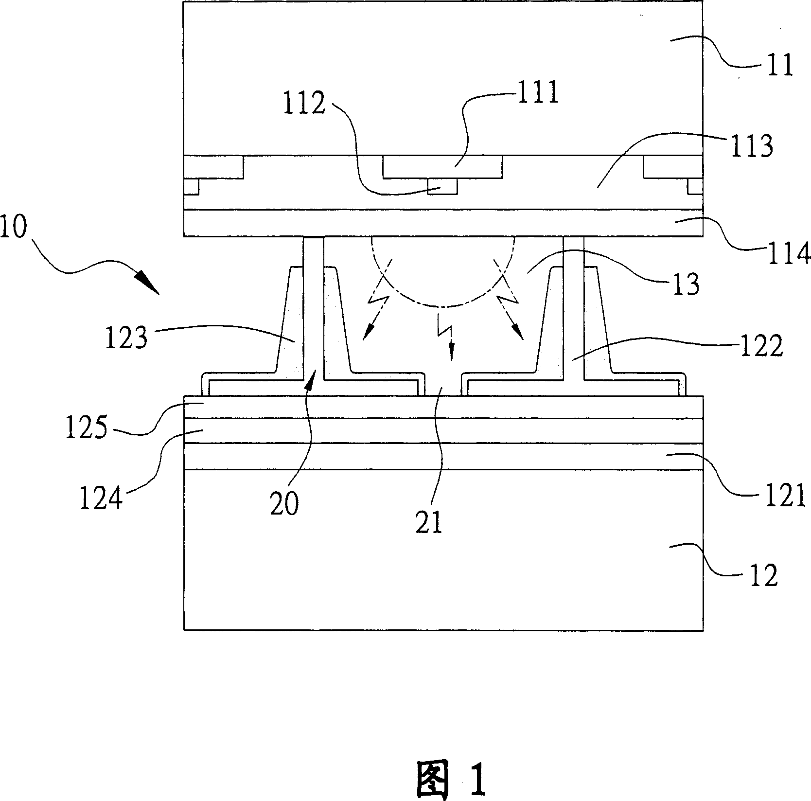
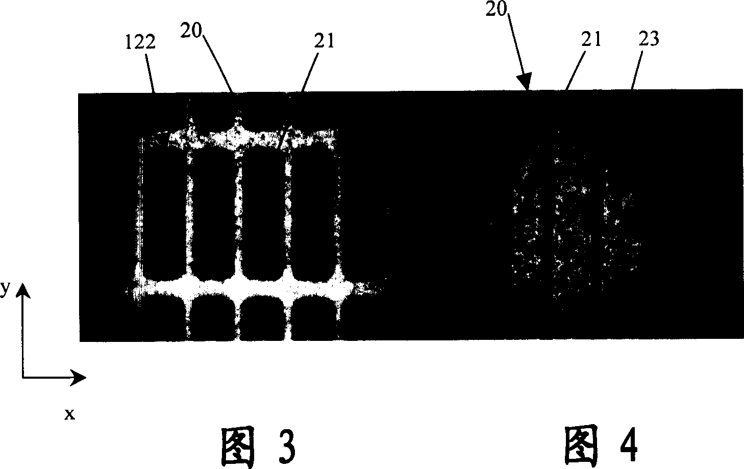
[0007] (2) For the shadow mask 20 made by double-sided etching, since the width and depth of the gas channel 23 are not easy to control during the etching process, as shown in FIG. In order not to affect the size of the shadow hole 21, it is generally possible to reduce the etching depth of the discharge cell 13 to increase the remaining thickness tm of the shadow mask 20 for etching to make the gas channel 23. The etching depth of 13 becomes shallower, and the coating area of ​​the phosphor is reduced, which in turn negatively affects the luminous efficiency of the discharge type plasma flat panel display.

Method used


Image

  • Method for making shadow mask of opposed-discharging type plasma plane display
  • Method for making shadow mask of opposed-discharging type plasma plane display
  • Method for making shadow mask of opposed-discharging type plasma plane display

Examples


Embodiment Construction

[0031] In order to make the purpose of the present invention, shape, structure device features and its effect easier to recognize and understand, the embodiments are given in conjunction with the drawings, and the detailed description is as follows:

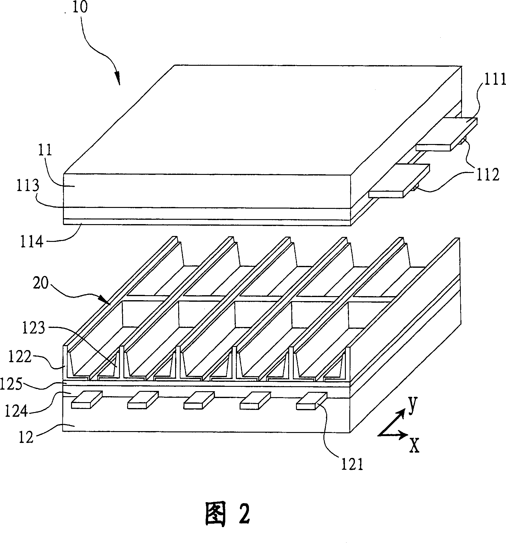
[0032]The invention relates to a manufacturing method of the shadow mask of the opposite discharge type plasma flat display, and the method is used for processing and manufacturing the shadow mask of the opposite discharge type plasma flat display. Before a shadow mask is not processed, as shown in Fig. 6, it is a thin metal plate 40, and the two side surfaces of this metal plate 40 are in a flat state. On one side surface of 40, along the vertical direction and the horizontal direction, a plurality of barrier walls 422 parallel to each other and at equal intervals are respectively etched, wherein a space surrounded by every four adjacent barrier walls 422 is the Facing a discharge cell 43 of the discharge type plasma flat panel ...


PUM


Abstract

The invention is for a making method for a kind of shield of plasma plane display of discharge type in opposite direction. The method is to take advantage of the etching process to etch respectively many obstructing walls that are parallel each other and with equidistant spacing on one side surface of one metal plate along the vertical and horizontal direction, and each four neighboring obstructing walls encloses a discharge unit, and a shading hole is etched in the center of each discharge unit whilst that runs through the metal plate; on the other side surface of the metal plate, at least a groove is made that puts through with the shading hole on the position of the relevant discharge unit by taking advantage of the rolling or punch process, and the neighboring grooves put through each other so as to form many air guide ditch on the other side surface. Thus, a shield that is necessary to the plasma plane display of discharge type in opposite direction is made simply and quickly, which can not only reduce the problems of the chemical pollutions caused by the traditional etching on both sides, but also improve the conformability rate of product as well as reduce the fabrication cost.

Description

technical field [0001] The present invention relates to a method for manufacturing a shadow mask of a facing discharge type plasma flat panel display, in particular to a method of utilizing a mechanical processing technology instead of a traditional etching process, so that on a shadow mask required by a facing discharge type plasma flat panel display, Simple and fast formation of multiple air guide channels. Background technique [0002] In the manufacturing technology of the traditional opposite AC discharge type (AC type for short) plasma flat panel display (Plasma DisplayPanel, PDP for short) 10, refer to as shown in Fig. 1, mainly make different active layers on two glass substrates 11,12, Then the peripheries of the two are sealed, and in each discharge unit (Cell) 13 therebetween, a special gas (such as: helium (He), neon (Ne), xenon (Xe) or argon ( Ar) etc.), in the structure of the plasma flat panel display shown in FIG. bus electrode) 112, a dielectric layer (die...

Claims


Application Information

Patent Timeline
IPC IPC(8): H01J9/14
Inventor 高旭彬梁建铮许胜文高旭佳
Owner MARKETECH INT
Learn More