
Cooling structure of solid thin-sheet laser

A thin-film laser, cooling structure technology, applied in lasers, laser parts, phonon exciters, etc., can solve the problems of large temperature gradient and explosion of laser medium, achieve good cooling effect, reduce deformation, and high heat transfer efficiency. Effect

Inactive Publication Date: 2007-05-30
SHANGHAI INST OF OPTICS & FINE MECHANICS CHINESE ACAD OF SCI
View PDF0 Cites 11 Cited by
  • Summary
  • Abstract
  • Description
  • Claims
  • Application Information

AI Technical Summary

Problems solved by technology

The rod-shaped gain medium will produce serious thermal lens effect under high average power operation, and at the same time, due to the limitation of cooling method, the temperature gradient inside and outside the laser medium will be too large to cause explosion

Method used


Image

  • Cooling structure of solid thin-sheet laser
  • Cooling structure of solid thin-sheet laser
  • Cooling structure of solid thin-sheet laser

Examples


Embodiment Construction

[0033] The method of the present invention will be described in detail below in conjunction with the accompanying drawings and embodiments.

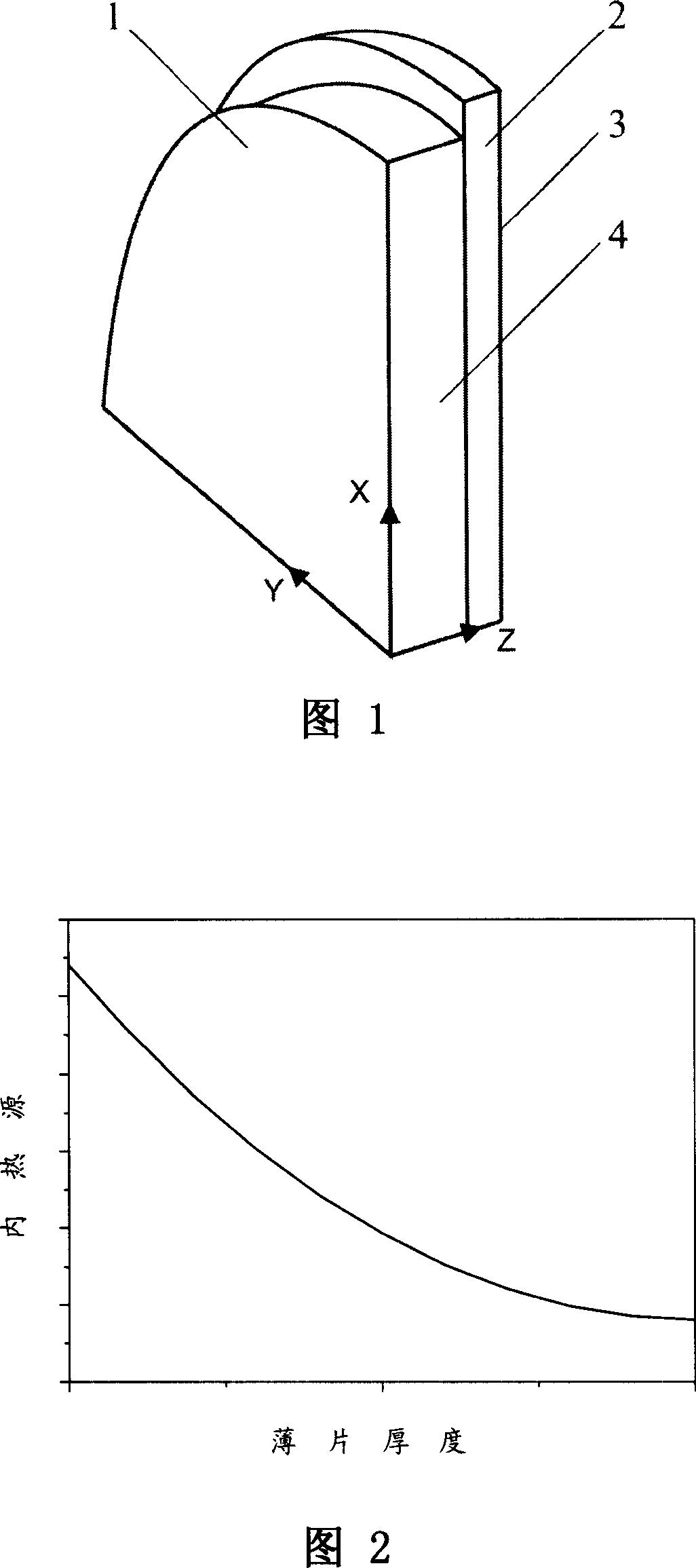
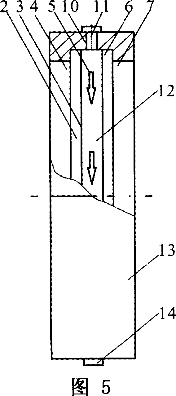
[0034] Referring to Fig. 4 and Fig. 5, Fig. 4 is an overall schematic diagram of the double sheet laser medium and diamond heat sink solid-state laser structure of the present invention, and Fig. 5 is a partial cross-sectional schematic diagram of an embodiment of the cooling structure of the present invention. As can be seen from Fig. 4, the cooling structure of the solid-state thin-film laser of the present invention is composed of a plurality of modules, wherein the composition of each module includes:

[0035] 1) Two pieces of left sheet laser medium 4 and right sheet laser medium 7 with the same size and performance, placed parallel and spaced apart. You can choose Yb:YAG crystal or Nd:YAG crystal flakes, or other laser media suitable for use as flake lasers. On the outer sides of the left sheet laser medium 4 and the right sheet l...


PUM


Abstract

This invention relates to one solid film laser cooling structure, which comprises several modules, wherein, each module is composed of two parallel gains medium films with certain distance; each module inside has cooling structure and the draw beam is sent to film medium from two sides of module; left medium film right side and film left side are added with two diamond heat sink to form one liquid cooling channel.

Description

technical field [0001] The invention relates to a solid sheet laser, in particular to a cooling structure for a solid sheet laser. technical background [0002] In the development of high average power solid-state lasers, the thermal effect of the laser medium has always been a major factor restricting the improvement of the laser energy and beam quality of the laser output. For continuously operating lasers, the temperature gradient brought about by real-time cooling can lead to undesirable effects such as thermal lensing, stress birefringence, and thermally induced depolarization. In order to improve and alleviate the non-uniform heat distribution in the laser medium, many ways can be adopted. [0003] One: using laser diode (Laser Diode, LD for short) pumping. Using LD to replace the traditional flash lamp to pump the solid laser medium can significantly reduce the waste heat in the medium, and has higher service life and efficiency. [0004] Second: change the geometr...

Claims


Application Information

Patent Timeline
IPC IPC(8): H01S3/042H01S3/16H01S3/0941
Inventor 侯立群祖继锋刘志刚周旭升尹宪华朱健强
Owner SHANGHAI INST OF OPTICS & FINE MECHANICS CHINESE ACAD OF SCI
Learn More