Apparatus of Plural Charged-Particle Beams

Active Publication Date: 2017-01-26
ASML NETHERLANDS BV
View PDF7 Cites 90 Cited by
  • Summary
  • Abstract
  • Description
  • Claims
  • Application Information

AI Technical Summary

Benefits of technology

This patent describes a new multi-beam apparatus that can observe a sample in different ways, such as varying the current and position of the probe spots. It uses a source-conversion unit to focus multiple beams onto the sample, and a plurality of electron optics elements to compensate for astigmatism and distortion aberrations. The apparatus can be used in the semiconductor manufacturing industry to inspect and review defects on wafers or masks. It can also adjust the current density and position of the primary-electron beam to vary the size of the probe spots. Overall, this apparatus provides high resolution and high throughput for observing samples in flexible conditions.

Problems solved by technology

For manufacturing semiconductor IC chips, pattern defects and / or uninvited particles (residuals) inevitably appear on a wafer and / or a mask during fabrication processes, which reduce the yield to a great degree.
Accordingly, the conventional yield management tools with optical beam gradually become incompetent due to diffraction effect, and yield management tools with electron beam are more and more employed.
Currently, the yield management tools with electron beam employ the principle of scanning electron microscope (SEM) with a single electron beam, which therefore can provide higher resolution but can not provide throughputs competent for mass production.
Although a higher and higher current of the single electron beam can be used to increase the throughputs, the superior spatial resolutions will be fundamentally deteriorated by the Coulomb Effect which increases with the beam current.
However, in this case, the deflection angles of the three beamlets become larger, which not only require stronger deflection powers of the three micro-deflectors but also generate larger deflection aberrations.
The first issue may incur electric breakdown of the three micro-deflectors, and the second issue may enlarge the sizes of the off-axis probe spots to an unacceptable level.

Method used


Image

  • Apparatus of Plural Charged-Particle Beams
  • Apparatus of Plural Charged-Particle Beams
  • Apparatus of Plural Charged-Particle Beams

Examples


Embodiment Construction

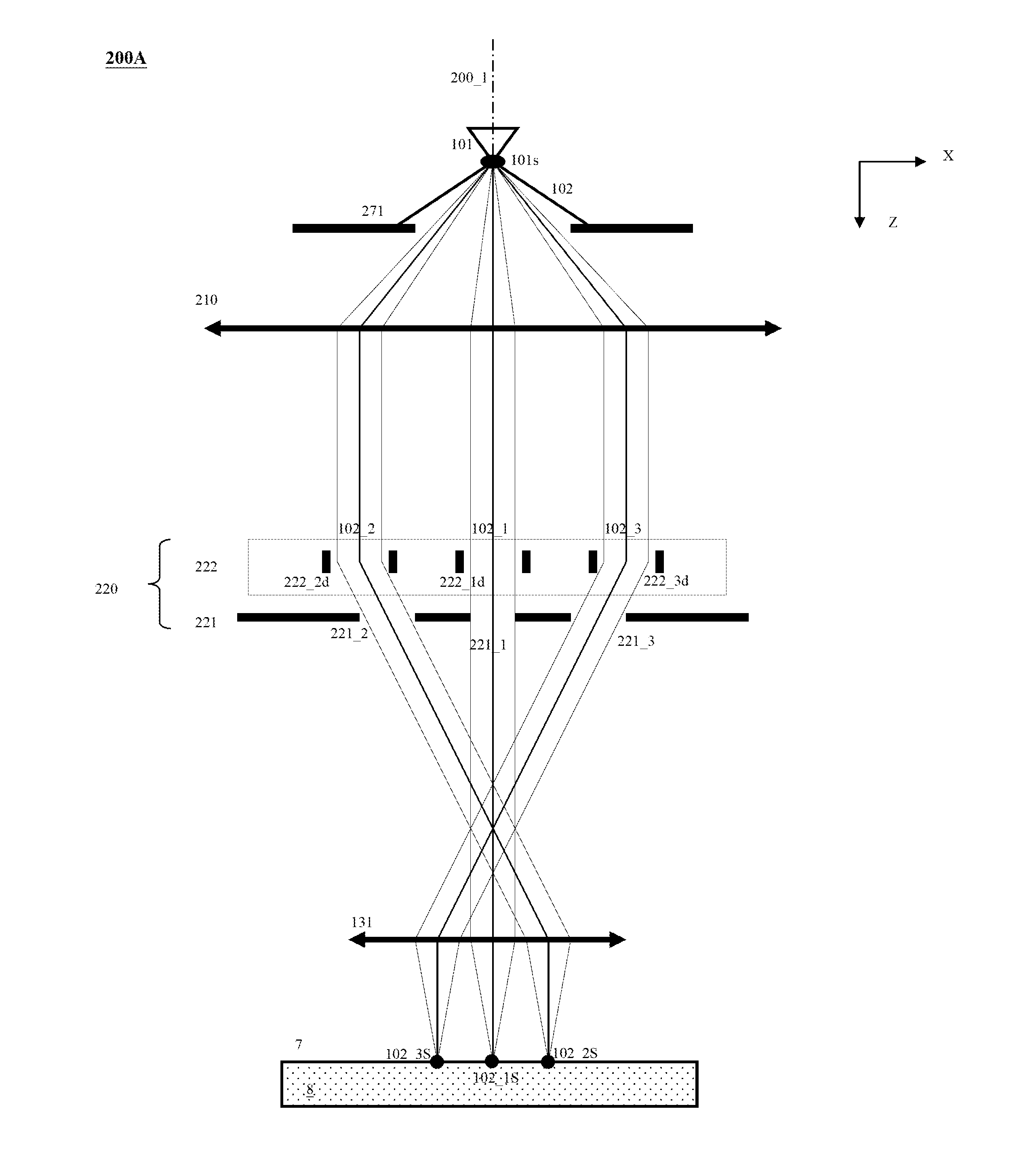
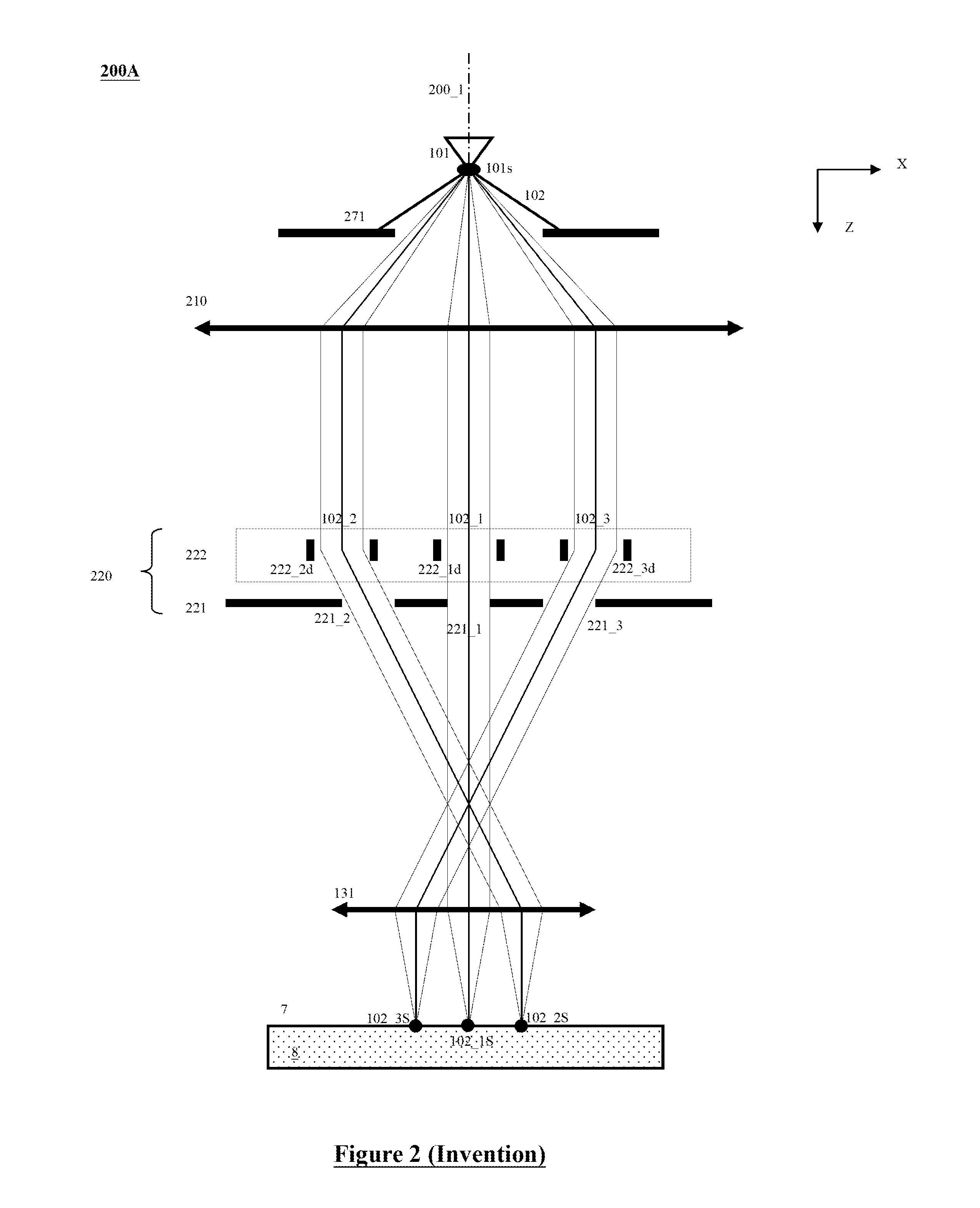
[0056]Various example embodiments of the present invention will now be described more fully with reference to the accompanying drawings in which some example embodiments of the invention are shown. Without limiting the scope of the protection of the present invention, all the description and drawings of the embodiments will exemplarily be referred to an electron beam. However, the embodiments are not used to limit the present invention to specific charged particles.

[0057]In the drawings, relative dimensions of each component and among every component may be exaggerated for clarity. Within the following description of the drawings the same or like reference numbers refer to the same or like components or entities, and only the differences with respect to the individual embodiments are described.

[0058]Accordingly, while example embodiments of the invention are capable of various modifications and alternative forms, embodiments thereof are shown by way of example in the drawings and wi...


PUM


Abstract

A multi-beam apparatus for observing a sample with high resolution and high throughput is proposed. In the apparatus, a source-conversion unit forms plural and parallel images of one single electron source by deflecting plural beamlets of a parallel primary-electron beam therefrom, and one objective lens focuses the plural deflected beamlets onto a sample surface and forms plural probe spots thereon. A movable condenser lens is used to collimate the primary-electron beam and vary the currents of the plural probe spots, a pre-beamlet-forming means weakens the Coulomb effect of the primary-electron beam, and the source-conversion unit minimizes the sizes of the plural probe spots by minimizing and compensating the off-axis aberrations of the objective lens and condenser lens.

Description

CLAIM OF PRIORITY[0001]This application claims the benefit of priority of U.S. provisional application No. 62 / 195,353 entitled to Ren et al. filed Jul. 22, 2015 and entitled “Apparatus of Plural Charged-Particle Beams”, the entire disclosures of which are incorporated herein by reference.CROSS REFERENCE TO RELATED APPLICATIONS[0002]This application is related to U.S. application Ser. No. 15 / 065,342 entitled to Weiming Ren et al. filed on Mar. 9, 2016 and entitled “Apparatus of Plural Charged-Particle Beams”, the entire disclosures of which are incorporated herein by reference.[0003]This application is related to U.S. application Ser. No. 15 / 078,369 entitled to Weiming Ren et al. filed on Mar. 23, 2016 and entitled “Apparatus of Plural Charged-Particle Beams”, the entire disclosures of which are incorporated herein by reference.[0004]This application is related to U.S. application Ser. No. 15 / 150,858 entitled to Xuedong Liu et al. filed on May 10, 2016 and entitled “Apparatus of Plur...

Claims


Application Information

Patent Timeline
IPC IPC(8): H01J37/147H01J37/10H01J37/06
CPCH01J37/1474H01J2237/1534H01J37/10H01J37/06H01J37/1475H01J37/1477H01J37/1478H01J37/12H01J37/141H01J37/145H01J37/28H01J2237/024H01J2237/0453H01J2237/0492H01J2237/103H01J2237/1205H01J2237/14H01J2237/1516H01J2237/1536
Inventor REN, WEIMINGLIU, XUEDONGHU, XUERANGCHEN, ZHONGWEI
Owner ASML NETHERLANDS BV
Why Eureka
Try Eureka