
Method for treating converter flue gas

A technology for converter flue gas and a treatment method, which is applied in the field of converter flue gas treatment, can solve the problems of large water consumption, difficult treatment and utilization of sludge, water pollution, etc., and achieves improved gas quality, good environmental protection effect, and water resource conservation. Effect

Inactive Publication Date: 2007-05-23
SHANDONG PROVINCE METALLURGICAL ENG CO LTD
View PDF0 Cites 13 Cited by
  • Summary
  • Abstract
  • Description
  • Claims
  • Application Information

AI Technical Summary

Problems solved by technology

[0003] The main disadvantages of the existing converter flue gas treatment methods are: 1. No matter adopting the so-called dry operation or the so-called wet operation, a large amount of water needs to be consumed, resulting in a large waste of precious water resources; 2. In the existing In the dry process system, the electrostatic precipitator is used as the follow-up dust removal work of the evaporative cooler. Due to the spark discharge of the electrostatic precipitator, during the process, when the columnar airflow mainly composed of gas and the columnar airflow mainly composed of air meet When there is a large interpenetration, there is a danger of deflagration (or explosion); 3. In the existing wet dust removal device, the water consumption is very large, there is a serious water pollution problem, and the sludge is difficult to treat and utilize; 4 .Existing converter flue gas treatment devices fail to recycle a large amount of physical sensible heat contained in the flue gas from 800 to 1000°C (or 550°C) to 200°C, which not only causes serious waste of water resources, but also causes waste of energy

Method used


Image

  • Method for treating converter flue gas

Examples


Embodiment Construction

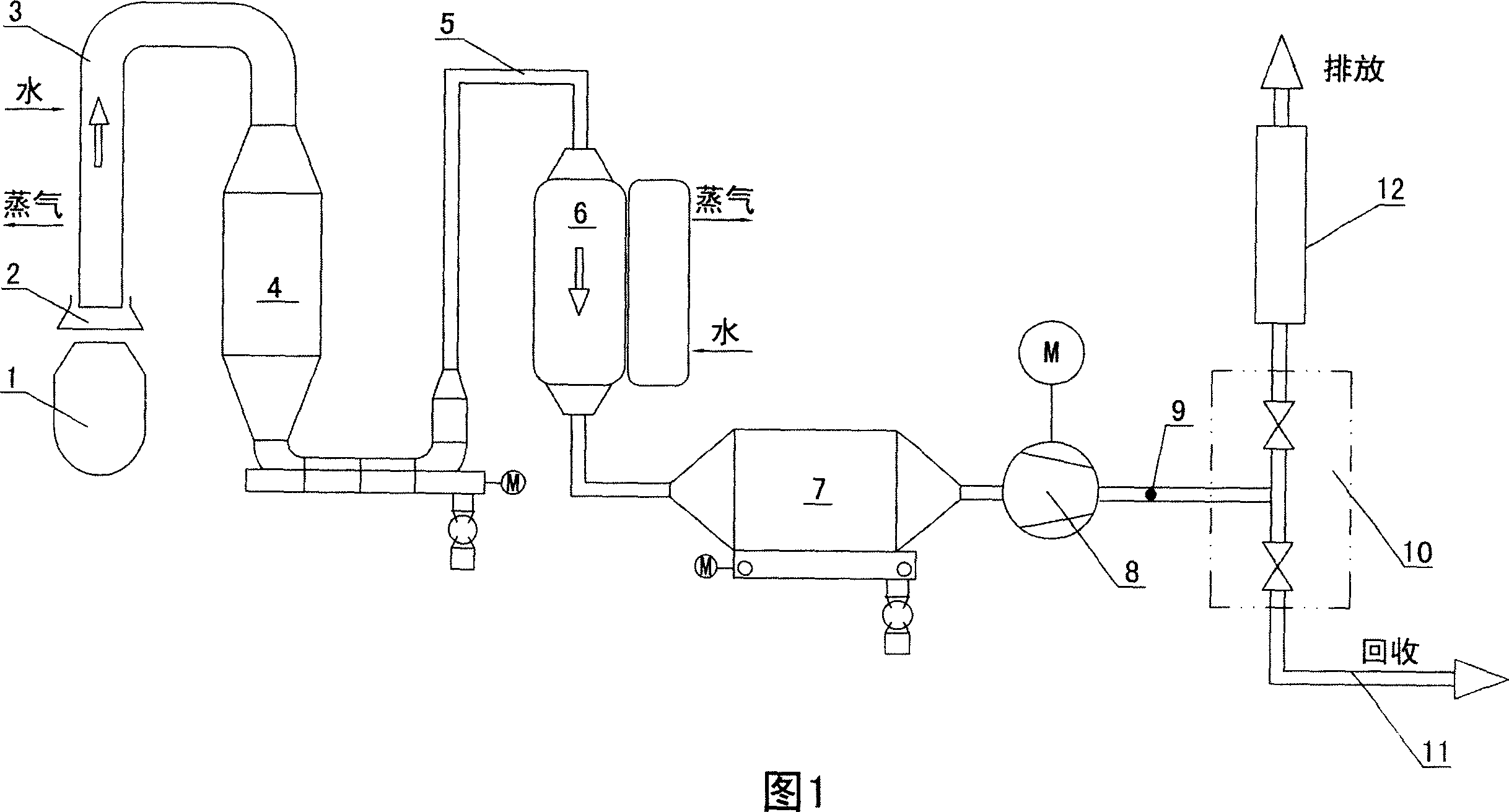
[0010] In the figure, 1 represents the converter, 2 represents the movable hood of the converter, 3 represents the waste heat boiler, 4 represents the gravity settling chamber, 5 represents the flue gas pipeline, 6 represents the high-efficiency inorganic heat pipe heat exchanger, 7 represents the bag filter, 8 represents the induction Fan, 9 represents gas component detection device, 10 represents switching station, 11 represents gas recovery pipe, 12 represents discharge chimney.

[0011] The steps of the method of the present invention are as follows: the flue gas produced by the converter 1 is captured by the movable hood 2 and enters the waste heat boiler 3. The waste heat boiler 3 is essentially a heat exchanger, and the converter flue gas The temperature drops to around 1000°C (~550°C). Then enter the gravity settling chamber 4 to remove 25~35% coarse dust (≥40um) particles. After that, the flue gas enters the high-efficiency inorganic heat pipe heat exchanger 6 throug...


PUM


Abstract

The invention provides a safe, energy saved, economical and reliable method for treating converter gas. The invent comprises the steps of: cooling the converter gas to 130-170DEG C with indirect heat exchange, removing dust to purify the converter gas, detecting the converter gas. If the converter gas meets the reserved detection standard, converter gas is recovered; otherwise, the converter gas is discharged. The invention avoids the bulk water consumption during the process of cooling by using the indirect heat exchanger to cool the gas, and recover the physical sensible heat discharged during the cooling process of gas from 550DEG C to 150DEG C.

Description

technical field [0001] The invention relates to a converter flue gas treatment method. Background technique [0002] The oxygen converter is the current mainstream steelmaking equipment. A large amount of dust-containing furnace gas is produced during the blowing process of the oxygen converter. Its temperature is about 1400-1600 ° C, and the CO content is as high as 90%. Usually, the movable cover skirt that can be raised and lowered is used to keep the furnace gas out of contact with the air as much as possible, and the gas extraction volume adjustment device is used to suppress the combustion of the furnace gas as little as possible (combustion coefficient α≤0.10), and then the flue gas is treated. The treatment of converter flue gas is an important means for industrial energy saving, water saving, negative energy steelmaking and environmental protection. The existing converter flue gas treatment method includes steps such as cooling and purifying the converter flue gas...

Claims


Application Information

Patent Timeline
IPC IPC(8): C21C5/46F27D17/00B01D46/02
CPCY02P10/25
Inventor 任浩魏新民刘利民李锐钱纲
Owner SHANDONG PROVINCE METALLURGICAL ENG CO LTD
Learn More