
High strength machine parts and shaft excellent in fatigue characteristics, and method for improving fatigue characteristics thereof

A technology for fatigue characteristics and mechanical parts, applied in the field of high-strength mechanical parts, which can solve problems such as difficulty in imparting large compressive residual stress, limitation of pellet size, and increased cost

Inactive Publication Date: 2007-04-25
NIPPON STEEL CORP
View PDF5 Cites 12 Cited by
  • Summary
  • Abstract
  • Description
  • Claims
  • Application Information

AI Technical Summary

Problems solved by technology

This method is to make the projection nozzle rotate around its central axis, and to arrange the opening direction of the projection hole relative to the nozzle central axis in a staggered manner without shielding and only carry out shot peening around the oil hole. However, covering is required, so the device becomes larger and the cost increases, and there is a problem that it is difficult to impart a large compressive residual stress due to the limitation of the size of the pellet.

Method used

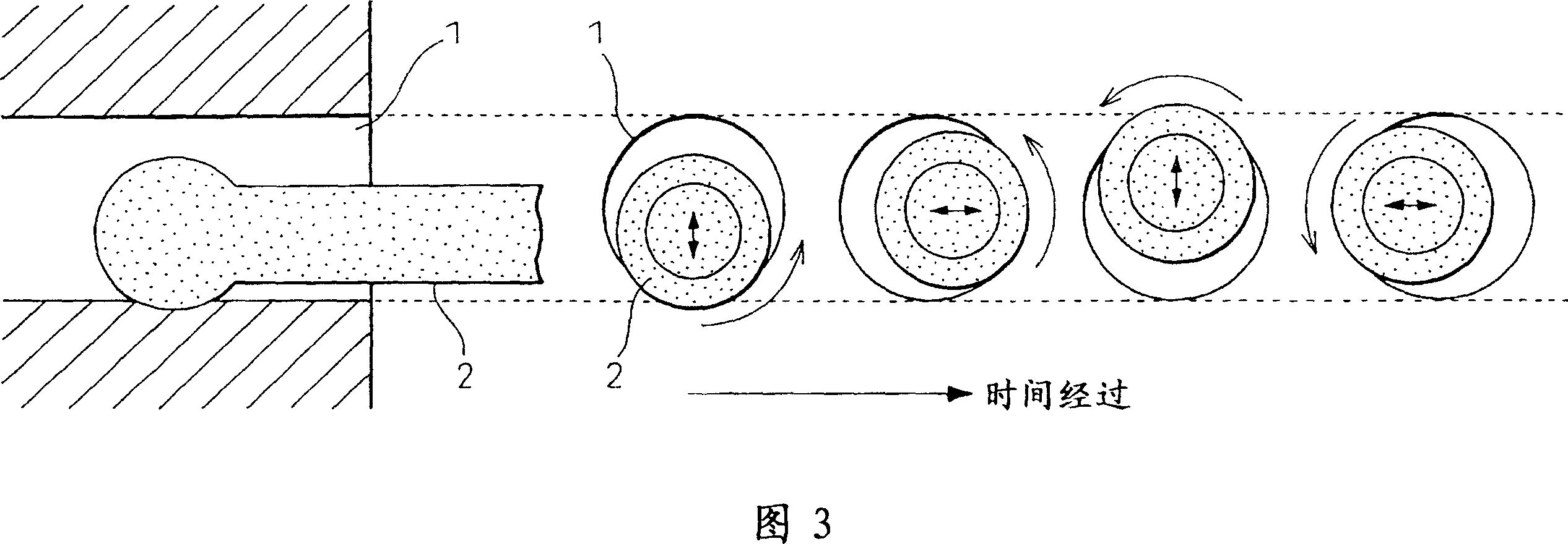

Image

  • High strength machine parts and shaft excellent in fatigue characteristics, and method for improving fatigue characteristics thereof
  • High strength machine parts and shaft excellent in fatigue characteristics, and method for improving fatigue characteristics thereof
  • High strength machine parts and shaft excellent in fatigue characteristics, and method for improving fatigue characteristics thereof

Examples


Embodiment 1

[0071] Hereinafter, the effects of the present invention will be more specifically described through examples.

[0072] Using steel materials with chemical compositions shown in Table 1, round bar-shaped members (shafts) as shown in FIG. 1 were produced by hot forging. The hot forging temperature is 1200°C. Then, by machining, it is finished into a mechanical part having notches shown in FIG. 1 . Then, using these machine parts, quenching-tempering treatment, high-frequency heating treatment, and carburizing treatment were performed, and the HV hardness of the surface was measured. The quenching-tempering treatment is carried out under conditions of a quenching temperature of 850 to 950°C and a tempering temperature of 180 to 650°C. The high-frequency heating treatment is quenching after heating to 950°C, and then tempering at 150°C. The carburizing treatment was carried out at a carburizing temperature of 950°C and a tempering temperature of 160°C. In addition, ultrasonic...

Embodiment 2

[0083] From the steel with the composition shown in Table 3, cut out a "Ono-type rotary bending test piece with a round hole" with a through hole to simulate an oil hole. The size of the test piece, the diameter of the parallel zone d = 12mm (JIS Z-2274, No. 1 Test piece, symbol 1-12), the diameter of the through hole is 2.4mm.

[0084] A test piece subjected to the ultrasonic treatment of the present invention and a comparison material without treatment or a treatment outside the range were prepared, and the Ono-type rotating bending fatigue test was performed to obtain fatigue strength. The results are shown in Table 4.

[0085] In addition, since this test piece is used in a simple bending fatigue test, fatigue cracks are generated from the surface layer of the hole, and fracture occurs on a surface perpendicular to the axial direction, so ultrasonic treatment is performed on the entire circumference of the surface layer around the hole.

[0086] The measured values ​​of r...


PUM

PropertyMeasurementUnit
depthaaaaaaaaaa
tensile strengthaaaaaaaaaa
radiusaaaaaaaaaa

Abstract

High strength machine parts excellent in fatigue strength which contain 0.1 to 1.2 mass % of C, and have a notch having a radius of curvature of 25 mm or less, wherein the surface thereof has an HV hardness of 250 or more and a surface layer of the notch has a compression residual stress of -100 to -1500 MPa; and a method for improving the fatigue strength thereof. A shaft excellent in fatigue resistance characteristics which comprises a steel product having a chemical composition, in mass %, that C: 0.1 to 1.2 %, Si: 0.05 to 2.5 %, Mn: 0.2 to 3 %, Al: 0.005 to 0.1 %, N: 0.001 to 0.02 % and the blance: Fe and inevitable impurities, and exhibiting a tensile strength of 800 MPa or more, characterized in that the shaft has an oil hole, and the surface layer of the oil hole has a compression residual stress of 50 to 90 % of the tensile strength of the above steel product; and a method for improving the fatigue strength thereof.

Description

technical field [0001] The present invention relates to high-strength mechanical parts excellent in fatigue characteristics such as shafts and gears widely used in automobiles and various industrial machines, and a method for improving the fatigue characteristics thereof. [0002] Specifically, it relates to a high-strength mechanical part having a notch with a curvature radius of 25 mm or less and having excellent fatigue properties with a surface HV hardness of 250 or more, and a method for improving the fatigue properties thereof. Background technique [0003] In order to reduce the weight and performance of automobiles and various industrial machinery, the demand for high strength of various mechanical parts is increasing. The high strength of such mechanical parts can be achieved by adjusting the chemical composition of steel and various heat treatment methods. ·condition. [0004] However, even if it is possible to increase the strength of a mechanical component, its ...

Claims


Application Information

Patent Timeline
Patent Type & Authority Applications(China)
IPC IPC(8): C22C38/00C21D1/04C22C38/06F16C3/02C22C38/58
Inventor 藤田崇史樽井敏三小泽修司越智达朗吉田卓
Owner NIPPON STEEL CORP
Learn More