Digital modulation argument adjusting instrument of optical fibre gyro based on FPGA

A technology of modulation amplitude and fiber optic gyroscope, applied in the direction of Sagnac effect gyroscope, optical waveguide coupling, etc., can solve the problems of reducing D/A converter stability, noise, increasing conversion error, etc., and achieve power saving The effects of consumption, volume reduction, and conversion error reduction

Inactive Publication Date: 2011-04-13
BEIHANG UNIV
View PDF0 Cites 0 Cited by
  • Summary
  • Abstract
  • Description
  • Claims
  • Application Information

AI Technical Summary

Problems solved by technology

Due to the analog approach, additional noise and offset errors are introduced
At the same time, since the reference voltage of the D / A converter is constantly changing, the stability of the D / A converter is reduced, and the conversion error is also increased.

Method used


Image

  • Digital modulation argument adjusting instrument of optical fibre gyro based on FPGA
  • Digital modulation argument adjusting instrument of optical fibre gyro based on FPGA
  • Digital modulation argument adjusting instrument of optical fibre gyro based on FPGA

Examples


Embodiment Construction

[0016] The present invention will be further described in detail below in conjunction with the accompanying drawings.

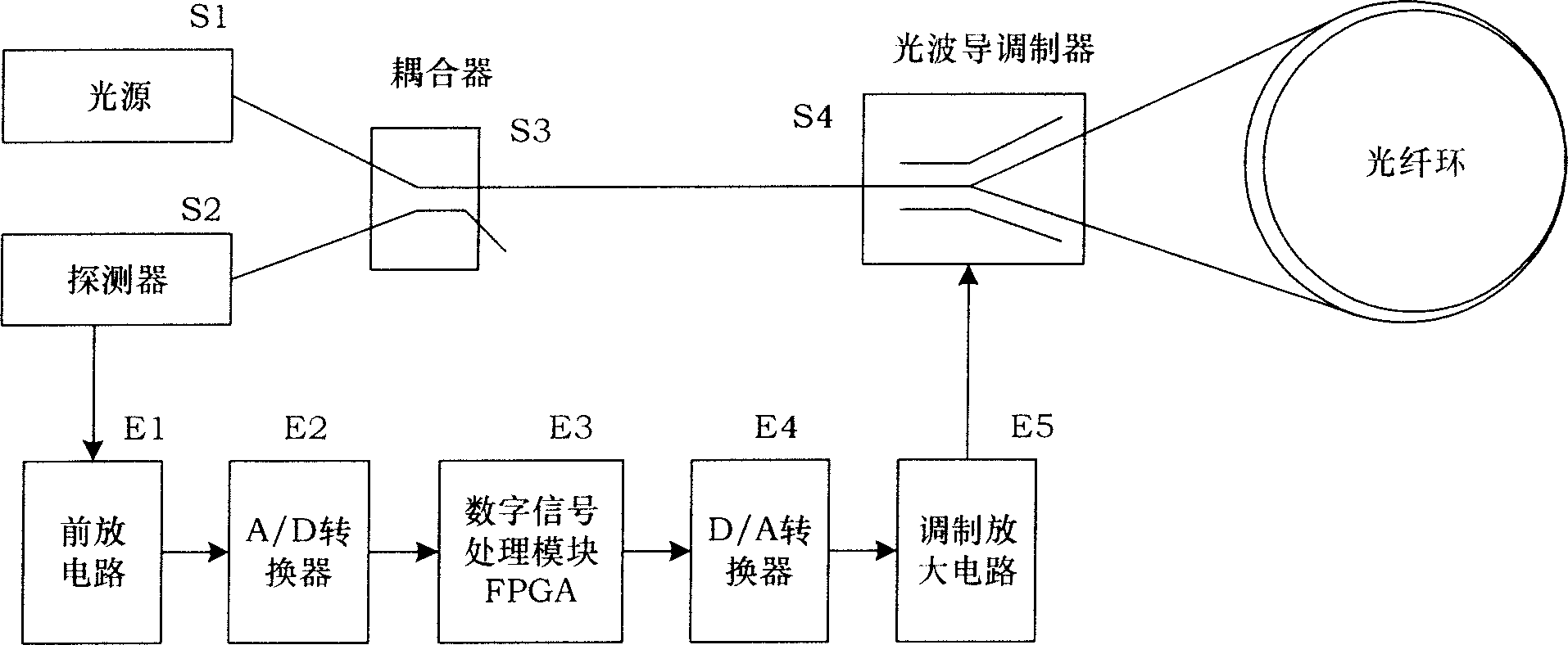
[0017] Please refer to Fig. 1, the present invention is a digital fiber optic gyro modulation amplitude adjustment device based on FPGA, the light emitted by light source S1 is incident into coupler S3, and two beams of light are separated through coupler S3, one of which is The optical waveguide modulator S4 is then divided into two beams of light that are respectively incident on the two ends of the fiber ring S5, and the two beams of light respectively circle the fiber ring S5 once and then synthesize a beam of light through the optical waveguide modulator S4 for interference; then pass through the coupler S3 is incident into the detector S2, and the electrical signal representing the optical power converted by the detector S2 is amplified and filtered by the pre-amplification circuit E1, and then the analog-to-digital conversion is performed by the A / D con...


PUM


Abstract

A amplitude adjustment device of degital optical circulator based on the FPGA is disclosed, the light come from the light source (S1) is incidengted into the coupler (S3), and two beams are obtained via the coupler (S3), one of the two beams is merotomized into two beams each of which is incidengted into the two ends of the fibre-optical ring (S5) via the optical waveguide modulator (S4), the twobeams are synthesized into one beam and interference after one loop circulating the fibre-optical ring (S5) and passing through the optical waveguide modulator (S4); then the beam is incidengted intothe detector (S2) via the coupler (S3), the electrical signal which expresses the optical power passes the front amplifying circuit (E1) to be enlarged and filted after the conversion in detector (S2), passes the A / D converter (E2) to complete the analogue / digital conversion to output the degital signal to the signal processing module (E3) which outputs the degital modulating signal to D / A converter (E4), the analog signal outputed is enlarged by the modulation amplifying circuit (E5) and is outputed to the optical waveguide modulator (S4). The invention makes the output voltage alignment circuit of the modulating step wave integrated just in one chip of FPGA processor, not getting involved in the simulation model. The attitude of the square wave uses the digital shift mode directly and is gained from the step wave resetting voltage. The square wave and the step wave is added directly in digital-sum in FPGA instead of adding in analog add circuit.

Description

technical field [0001] The present invention relates to a device for adjusting the modulation amplitude of a fiber optic gyroscope, more particularly, a device for adjusting the modulation amplitude of an interferometric closed-loop fiber optic gyroscope based on an FPGA for the generation of a modulated step wave. Background technique [0002] In the closed-loop feedback process of the fiber optic gyroscope, it is necessary to use a ladder wave for feedback modulation, so that the reset voltage V of the ladder wave output F equal to the 2π phase voltage V of the integrated optical modulator PR , and the square wave voltage V S equal Phase voltage Due to the 2π phase voltage V of each integrated optical modulator PR There are differences, in the process of using V PR will also change, so the feedback modulation circuit of the fiber optic gyroscope is required to be able to adjust the reset voltage V of the ladder wave F and square wave voltage V S , so that the rese...

Claims


Application Information

Patent Timeline
Patent Type & Authority Patents(China)
IPC IPC(8): G01C19/72G02B6/24
Inventor 金靖田海亭潘雄
Owner BEIHANG UNIV
Why Eureka
Try Eureka