
Fast forming laser diode energy source and device for same

A technology of laser diodes and forming equipment, applied in lasers, laser parts, semiconductor lasers, etc., can solve the problems of large volume, fixed spectrum and poor reliability of gas lasers, and achieve the effects of low price, reduced system cost and reliable operation.

Inactive Publication Date: 2007-03-14
ZHONGBEI UNIV
View PDF0 Cites 16 Cited by
  • Summary
  • Abstract
  • Description
  • Claims
  • Application Information

AI Technical Summary

Problems solved by technology

These gas lasers are bulky, unreliable, short-lived, and have a fixed spectrum and are not optional

Method used


Image

  • Fast forming laser diode energy source and device for same
  • Fast forming laser diode energy source and device for same
  • Fast forming laser diode energy source and device for same

Examples


Embodiment Construction

[0036] The specific embodiment of the present invention (utility model) will be described below in conjunction with the accompanying drawings.

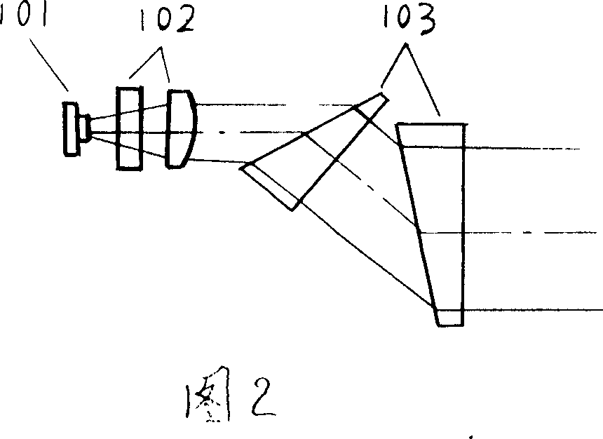
[0037] As shown in Figure 2, it is a laser diode energy source for rapid prototyping; the light source is a laser diode LD101, and the astigmatic beam output by the laser diode LD light source is collimated by a cylindrical lens group 102 to become a parallel beam, and then the beam expander 103 expands the slow axis The parallel beam is expanded, and the astigmatic beam output by the laser diode light source is collimated and expanded into a circular parallel beam.

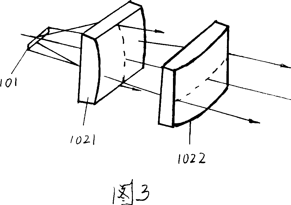
[0038] Wherein: the cylindrical mirror group includes a fast-axis collimating cylindrical mirror 1021 and a slow-axis collimating cylindrical mirror 1022, and the bus lines of the fast-axis collimating cylindrical mirror and the slow-axis collimating cylindrical mirror are perpendicular to each other. In the slow-axis plane of the diode LD light source, the fast-axis col...


PUM


Abstract

The related fast-forming laser diode energy source comprises: a source LD, a column mirror group included a fast-axis and slow-axis collimation column mirror with bus-bar vertically, a beam expander to expand the slow-axis parallel beam to let beam diameter at two directions as same cycle, and a frame or shell. Besides, it also contains a direction indicator, a beam-joining device, a coupled expander, a dynamic focus module, and an x-axis / y-axis scanning mirror. This invention has small size and well reliability.

Description

1. Technical field [0001] The invention belongs to the technical field of rapid prototyping in mechanical engineering, and mainly relates to a laser diode energy source for rapid prototyping equipment. 2. Technical Background [0002] Since the world's first commercial rapid prototyping machine came out in 1988, rapid prototyping technology (RPT) has made great progress. At present, the main equipment and process methods that have been put into use in the world are as follows: Selective photocuring ( SLA, also known as three-dimensional printing method), selective laser sintering (SLS), layered solid method (LOM, also known as paper cutting method) and selective laser sintering method (FDM). The above four commonly used rapid prototyping (RP) process methods have their own advantages and disadvantages, and are suitable for different processing objects and conditions. The first three processes all use laser as an energy source, so they are also called laser rapid prototyping...

Claims


Application Information

Patent Timeline
Patent Type & Authority Applications(China)
IPC IPC(8): G02B27/09H01S5/00
Inventor 朱林泉马巧梅靳雁霞
Owner ZHONGBEI UNIV
Learn More