


Quick Research
Generate reliable direction feasibility study reports for your R&D in just a few steps.

Technical Q&A
Discover and master advanced knowledge NOW. Basics, ideas, possibilities, all at once.

Find Solutions
As an expert in R&D theories, this can generate solutions to your technical problems instantly.

Evaluate Feasibility
Analyze your overall solution with one click, know your potential R&D risks in advance.

Monitor Landscape
Get weekly tech updates, stay abreast of the latest tech innovations and key insights.
Anisotropic binding rare earth permanent magnet oriontation shaping device
A technology of rare earth permanent magnets and orientation molding, which is applied in the direction of molding indenters, etc., can solve the problems of not being able to obtain ideal demagnetization, and achieve the effects of increasing unit weight density and uniformity, improving magnetic properties, and low-cost manufacturing performance
- Summary
- Abstract
- Description
- Claims
- Application Information
AI Technical Summary
Problems solved by technology
Method used
Image

Examples
specific Embodiment approach 1
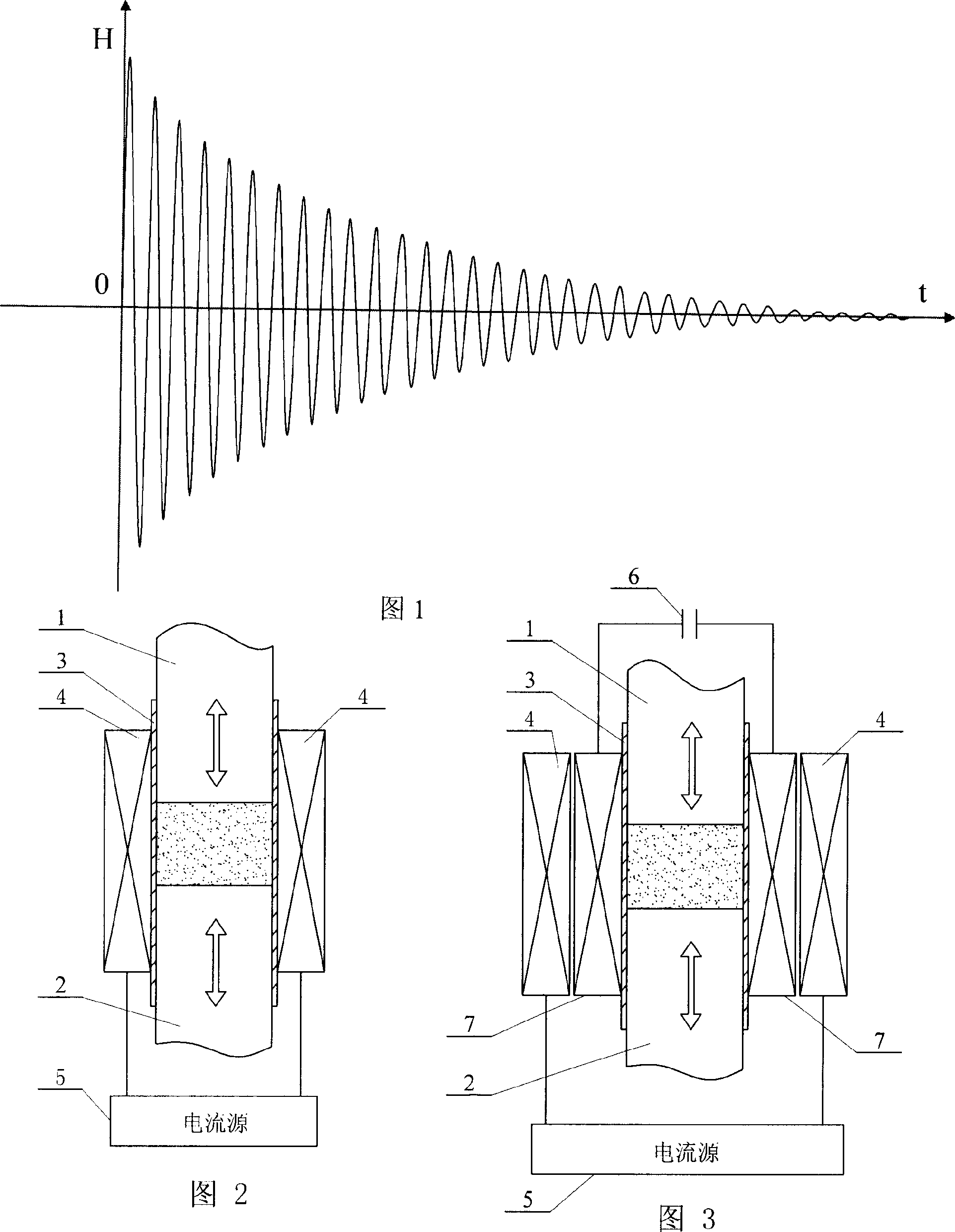
[0010] Specific embodiment one: (see Fig. 1, Fig. 2, Figure 6 ) This embodiment consists of upper die punch 1, lower die punch 2, die sleeve 3, coil 4 and current source 5, the lower end of upper die punch 1 and the upper end of lower die punch 2 are respectively placed in the mold The upper and lower parts of the sleeve 3, the outside of the mold sleeve 3 is wound with a coil 4, the two ends of the coil 4 are respectively connected to the two terminals of the current source 5, and the current generated by the current source 5 is passed into the coil 4 A sinusoidal oscillating damping magnetic field is formed.
specific Embodiment approach 2
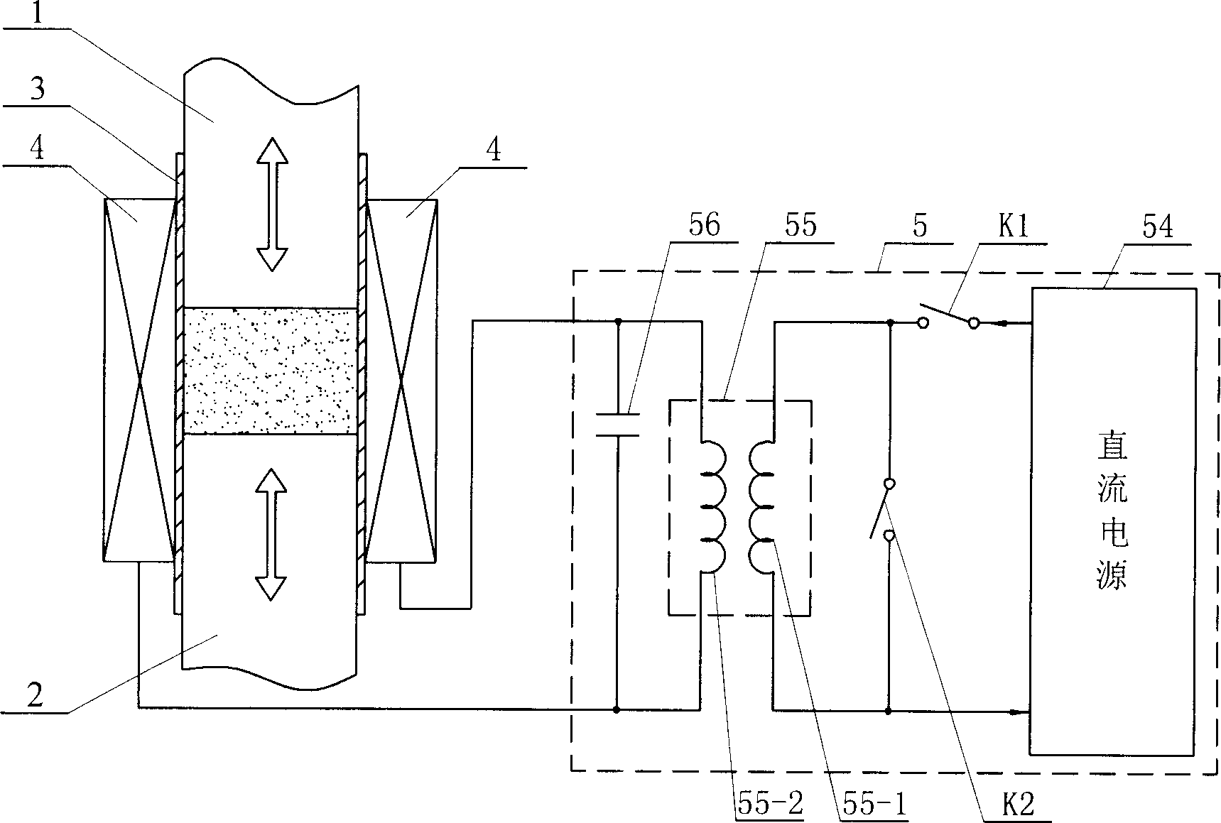
[0011] Specific embodiment two: (referring to Fig. 3) the difference between this embodiment and specific embodiment one is that it also comprises the 3rd electric capacity 6 and No. Between the inner winding surfaces of the coil 4, the ninth coil 7 and the third capacitor 6 form a closed loop; the current source 5 is a pulse power supply. Other compositions and connections are the same as in the first embodiment.
specific Embodiment approach 3
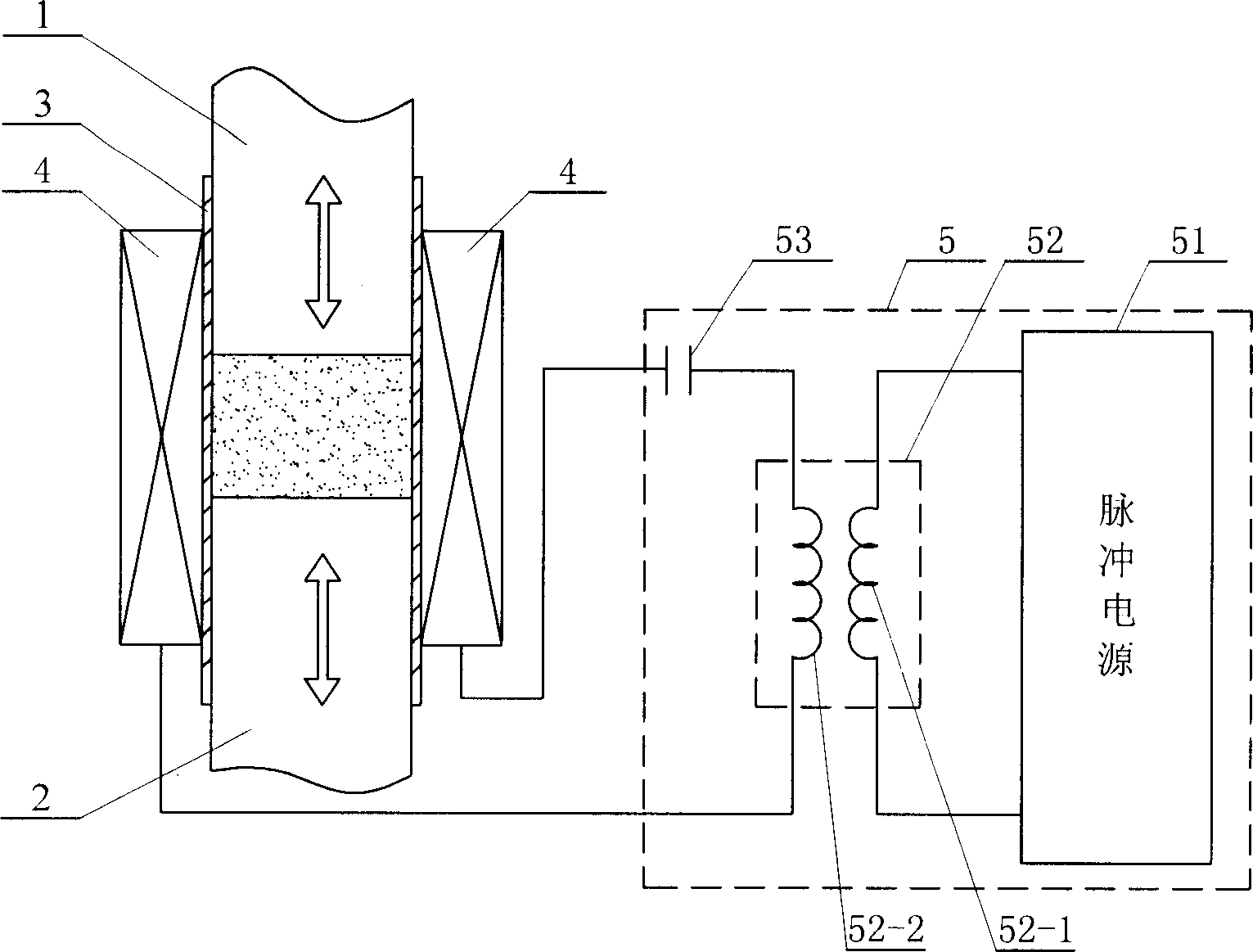
[0012] Specific implementation mode three: (see Figure 4 ) The difference between this embodiment and the specific embodiment one is that the current source 5 is composed of a pulse power supply 51, a first mutual induction solenoid 52, and a first capacitor 53, and the first mutual induction solenoid 52 is formed by the first The primary coil 52-1 is composed of the first secondary coil 52-2, the first end of the first primary coil 52-1 is respectively connected to the two output ends of the pulse power supply 51, and one end of the first secondary coil 52-2 is connected to the first One end of the capacitor 53 is connected; the two ends of the coil 4 are respectively connected to the other end of the first secondary coil 52 - 2 and the other end of the first capacitor 53 . Other compositions and connections are the same as in the first embodiment.
PUM
 Abstract
Description
Claims
Application Information
 - R&D Engineer
- R&D Manager
- IP Professional
- Industry Leading Data Capabilities
- Powerful AI technology
- Patent DNA Extraction
Browse by: Latest US Patents, China's latest patents, Technical Efficacy Thesaurus, Application Domain, Technology Topic, Popular Technical Reports.
© 2024 PatSnap. All rights reserved.Legal|Privacy policy|Modern Slavery Act Transparency Statement|Sitemap|About US| Contact US: help@patsnap.com